Method for calibrating a rotary encoder

a rotary encoder and encoder technology, applied in the direction of speed/acceleration/shock measurement, instruments, material analysis, etc., can solve the problems that the tracks provided by the two sensors do not correspond to the optimal sine or cosine function, and achieve the effect of improving the angular resolution of the electric machin

Active Publication Date: 2015-09-03
BAUMULLER NURNBERG GMBH
View PDF3 Cites 14 Cited by
  • Summary
  • Abstract
  • Description
  • Claims
  • Application Information

AI Technical Summary

Benefits of technology

[0016]Provided a local minimum of the amplitude as a function of the correction factor is used as the limiting value, the adjustment, therefore the addition of the specific value to the correction factor, occurs expediently until the amplitude increases. In such a case, the correction factor is decreased once by the specific value and the method is ended. An implementation of the method can be carried out relatively efficiently by means of the iterative approach, because no complicated calculations for determining the correction factor itself are necessary. In fact, the number of arithmetic operations increase but these are relatively simple to carry out. Further, a stable correction factor is found after even a relatively low number of iterations steps.
[0017]In an embodiment of the invention, the angular velocity can be used as the angular progression over time. In other words, the oscillation within the angular velocity is identified, which is possible relatively easily, because for this purpose only the angular velocity needs to be subtracted from the specific speed to which the electric machine is regulated.
[0022]If the phase difference of the oscillation and the sine track is less than ±90°, suitably the offset of the sine track is increased. In other words, the offset of the sine track is used as the correction factor and is increased if the oscillation leads the sine track in the angular progression over time by less than 90° or lags behind by less than 90°. The procedure is similar, for example, with the cosine track in order to calibrate it. In particular, if the adjustment of the tracks occurs iteratively, the particular offset is therefore increased or reduced by a specific, previously established value. A relatively simple determination of the correction factor is made possible in this way, without complex calculations having to be performed.
[0025]By means of the adjustment of the amplitudes to one another and especially to a previously established amplitude, further oscillations in the angular progression over time, whose frequency corresponds to double the product of the specific speed and the line count, are avoided or at least reduced. For example, the amplitudes after the adjustment are not modified further. Alternatively, it is also possible to use the amplitude as an especially additional correction factor, and by means of an adjustment of the amplitude to prevent an oscillation in the angular progression over time with a frequency of double the product of the specific speed and the line count or at least to reduce the amplitude of this oscillation.
[0028]Expediently, a constant speed is used as the specific speed to which the electric machine is regulated. For example, the specific speed is selected such that the frequency of the oscillation is between 50 Hz and 200 Hz. If the rotary encoder has a line count of 1024, and the product of the specific speed and the line count is used as the frequency, the specific speed is therefore between 2.9 revolutions per minute (rpm) and 12 rpm. It is assured in this way that the rotor of the electric machine runs substantially uniformly and the oscillation determined in the angular progression over time is not caused by an acceleration or deceleration of the rotor.

Problems solved by technology

Because of fabrication tolerances of the rotary encoder, however, the tracks provided by the two sensors do not correspond to an optimal sine or cosine function.
When the unit circle is deformed to form an ellipse, there is accordingly an amplitude error, when the ellipse is tilted there is a phase error, and when the circle is shifted with respect to the origin an offset error of the rotary encoder.

Method used


Image

  • Method for calibrating a rotary encoder
  • Method for calibrating a rotary encoder
  • Method for calibrating a rotary encoder

Examples


Embodiment Construction

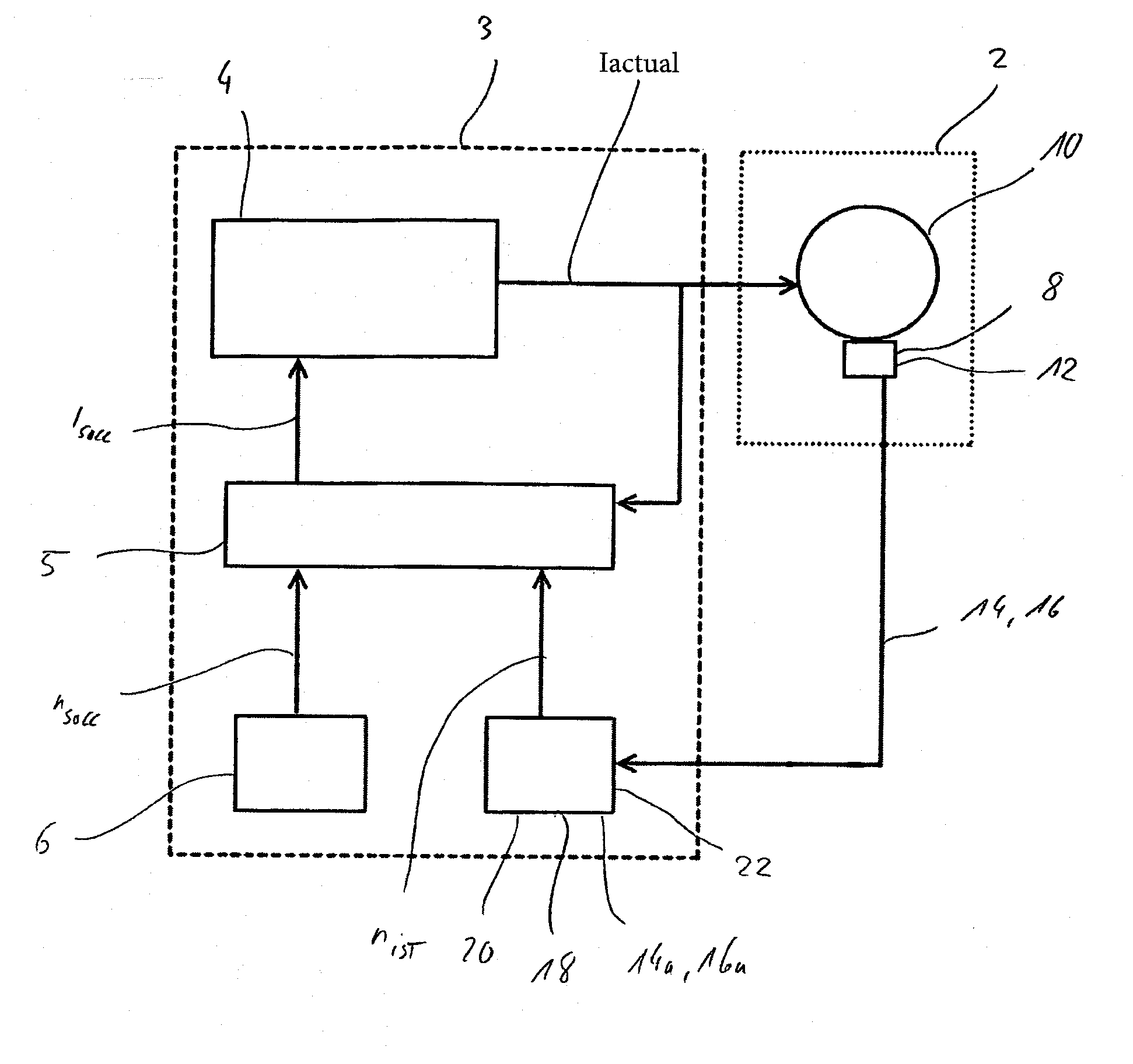
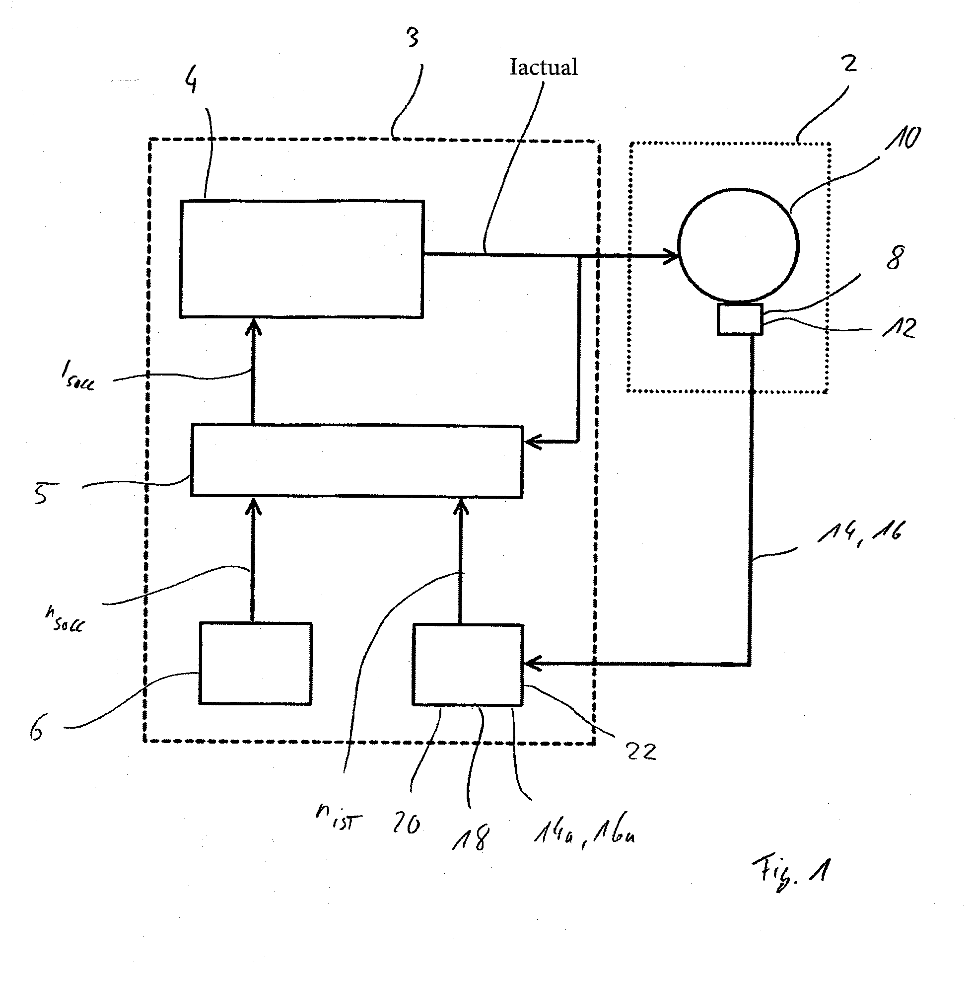
[0038]An electric motor 2, which is supplied by means of a converter 3 with a three-phase alternating current Iactual, is shown schematically in FIG. 1. Converter 3 itself is driven by means of a current controller 4 and a rotational speed controller 5, which is supplied both with the value of the alternating current Iactual and a current rotational speed nactual of electric motor 2 and a specific speed ntarget. A target current Itarget is calculated from these data and sent to current controller 4, according to whose specifications current valves (not shown) of converter 3 are operated. The specific speed ntarget in this case is preset, depending on the requirements for electric motor 2, by means of a target value setting unit 6 but also if a calibration of electric motor 2 is started.

[0039]The current rotational speed nactual is determined via an incremental encoder 8 operating according to a photoelectric principle, which is flange-mounted on the B-side on a shaft of a rotor / stat...


PUM


Abstract

A method for calibrating a rotary encoder, in particular an incremental encoder, of an electrical machine, wherein the encoder has a number of reference marks and outputs a sine track and a cosine track. The electrical machine can be regulated to a specific speed, an angle of the electrical machine is determined with the aid of the sine track and / or the cosine track, from this an angular progression over time is ascertained, an oscillation in the angular progression over time with a frequency of substantially one integral multiple of the product of the specific speed and the number of reference marks is ascertained, and from this a correction factor the sine track and / or the cosine track is derived, wherein the amplitude of the oscillation is less than or equal to a limiting value. The invention further relates to an encoder evaluation and an electric motor having a rotary encoder.

Description

[0001]This nonprovisional application is a continuation of International Application No. PCT / EP2012 / 004713, which was filed on Nov. 14, 2012, and which is herein incorporated by reference.BACKGROUND OF THE INVENTION[0002]1. Field of the Invention[0003]The invention relates to a method for calibrating a rotary encoder, particularly an incremental encoder, of an electric machine, the encoder outputting a sine track and a cosine track. The invention relates further to an encoder evaluation for carrying out the method and to an electric machine.[0004]2. Description of the Background Art[0005]In machines driven by an electric motor such as, for example, machine tools, the current phase position of the electric motor must be known for the precise operation of the machine. Thus, for example, the accurate metering of plastic in an injection molding machine or the correct pressure by an offset printing press supplied with paper rolls is only possible, if the current angle of the rotor with r...

Claims


Application Information

Patent Timeline
Patent Type & Authority Applications(United States)
IPC IPC(8): G01D18/00G01D5/347
CPCG01D5/3473G01D18/00G01D5/2448G01P21/02G01D18/001
Inventor SCHINDLER, ACHIM
Owner BAUMULLER NURNBERG GMBH
Why Eureka
Try Eureka