Compensation of defective beamlets in a charged-particle multi-beam exposure tool

a multi-beam exposure and beamlet technology, applied in the direction of irradiation devices, electric discharge tubes, electrical apparatus, etc., can solve the problems of inability to store the complete rasterized image data, the number of pixels required to obtain a sufficiently good feature resolution at standard chip sizes is quite high, and the pd device is generally non-ideal, so as to achieve the effect of increasing the correction quality

Active Publication Date: 2015-09-03
IMS NANOFABTION
View PDF3 Cites 31 Cited by
  • Summary
  • Abstract
  • Description
  • Claims
  • Application Information

AI Technical Summary

Benefits of technology

[0028]In certain situations, it becomes necessary to use not only the IELs directly next to the defective IEL as correction IELs, but also more distant IELs. This dramatically increases the correction quality if the direct neighbor IELs are already at or near their minimum or maximum exposure level. The algorithm chooses

Problems solved by technology

The number of pixels required to obtain a sufficiently good feature resolution at standard chip sizes is quite high and remains a challenging task.
Therefore, the storage of the complete rasterized image data is not feasible.
A common problem to be solved is that the PD device is generally non-ideal, which means that a (small) number of the apertures will not work as designed.
A faulty aperture may be physically blocked

Method used


Image

  • Compensation of defective beamlets in a charged-particle multi-beam exposure tool
  • Compensation of defective beamlets in a charged-particle multi-beam exposure tool
  • Compensation of defective beamlets in a charged-particle multi-beam exposure tool

Examples


Embodiment Construction

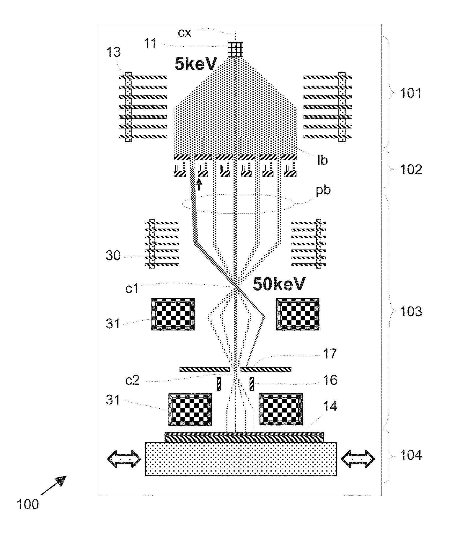
[0078]One embodiment of the invention discussed in the following is a development from the particle-beam exposure apparatus of PML2 and eMET type with a pattern definition (PD) system as disclosed in U.S. Pat. No. 6,768,125 and U.S. Pat. No. 7,781,748 of the applicant, and with a large-reduction projecting system. In the following, first the technical background of the apparatus is discussed—as far as relevant to many embodiments of the invention—, then certain embodiments of the invention are presented in detail.

[0079]It should be appreciated that the invention is not restricted to the following embodiments or the particular layout of the PD system, which merely represent one of the possible applications of the invention; embodiments of the invention are suitable for other types of processing systems that use a multi-beam setup for exposure of a target.

Charged-Particle Multi-Beam System

[0080]A schematic overview of an charged-particle multi-beam mask exposure tool (mask writer) emp...


PUM


Abstract

An exposure pattern is computed which is used for exposing a desired pattern on a target by means of a blanking aperture array in a particle-optical lithography apparatus which has a finite number of defects, said desired pattern being composed of a multitude of image elements within an image area on the target: A list of defective blanking apertures is provided, comprising information about the type of defect of the defective blanking apertures; from the desired pattern a nominal exposure pattern is calculated as a raster graphics over the image elements disregarding the defective blanking apertures; the “compromised” image elements (1105) are determined which are exposed by aperture images of defective blanking apertures; for each compromised element (1105), a set of neighboring image elements is selected as “correction elements” (1104); for each compromised element, corrected dose values are calculated for the correction elements, said corrected dose values minimizing an error functional of the deviation of the dose distribution including the defects from the nominal dose distribution, under the constraint that each of the corrected dose values falls within the allowed doses; and a corrected exposure pattern (1103) is generated by substituting the corrected dose values for the nominal dose values at the correction elements.

Description

RELATED APPLICATIONS[0001]This application claims priority to European Patent Application 14157259.4 filed Feb. 29, 2014, the disclosure of which is incorporated herein by reference in its entiretyFIELD OF THE INVENTION[0002]Embodiments of the present invention relates to a method for computing an exposing pattern for exposing a desired pattern on a surface of a target in a particle-beam exposure tool, as well as a method for forming a desired pattern on a surface of a target incorporating the computing method, designed to take into account certain defects that may be present in the exposure tool, that is, in the blanking aperture array used in the exposure tool to define the pattern.[0003]In a specific application, embodiments of the invention is applied to a method for irradiating a target with a beam of energetic radiation formed by electrically charged particles, which comprises the steps of:[0004]providing a pattern definition means having a plurality of apertures transparent t...

Claims


Application Information

Patent Timeline
IPC IPC(8): H01J37/317H01J37/04
CPCH01J37/3177H01J2237/0435H01J2237/31715H01J37/045H01J37/3026H01J2237/31798H01J2237/3175
Inventor REITER, RAFAELPLATZGUMMER, ELMARSCHIESSEL, KLAUS
Owner IMS NANOFABTION
Why Eureka
Try Eureka