Wireless inductive power transfer

a technology of inductive power transfer and wireless, which is applied in the direction of exchanging data chargers, inductances, transportation and packaging, etc., can solve the problems of inconvenient use, impracticality, and battery use, and achieve low complexity operation, efficient signaling, and low complexity operation.

Active Publication Date: 2015-09-03
KONINKLJIJKE PHILIPS NV
View PDF0 Cites 32 Cited by
  • Summary
  • Abstract
  • Description
  • Claims
  • Application Information

AI Technical Summary

Benefits of technology

[0075]This may provide efficient yet low complexity operation. In accordance with an optional feature of the invention, the power receiver is arranged to transmit the first message d

Problems solved by technology

However, this tends to be impractical and requires the user to physically insert connectors or otherwise establish a physical electrical contact.
It also tends to be inconvenient to the user by introducing lengths of wire.
Although, the use of internal batteries may avoid the need for a wired connection to a power supply during use, this only provides a partial solution as the batteries will need recharging (or replacing which is expensive).
The use of batteries may also add substantially to the weight and potentially cost and size of the devices.
However, such a bidirectional link is not trivial to include and is subject to a large number of difficulties and challenges.
Furthermore, the technical restrictions in terms of e.g. modulation options, power variations, transmission options etc. are very restrictive as they need to fit in with the existing parameters.
Accordingly, many challenges and difficulties are associated with enhancing a power transfer system such as Qi to include bidirectional communication.
However, there are scenarios where the power transfer system does not operate optimally.
However, if a power receiver device is e.g. permanently placed on the power transmitter, there is no initiating event, and the power receiver may remain in the selection phase and not be able to re-enter the power transfer phase.
This may be a problem for devices that need repowering at intervals.
However, as the system is in the selection phase it

Method used


Image

  • Wireless inductive power transfer
  • Wireless inductive power transfer
  • Wireless inductive power transfer

Examples


Embodiment Construction

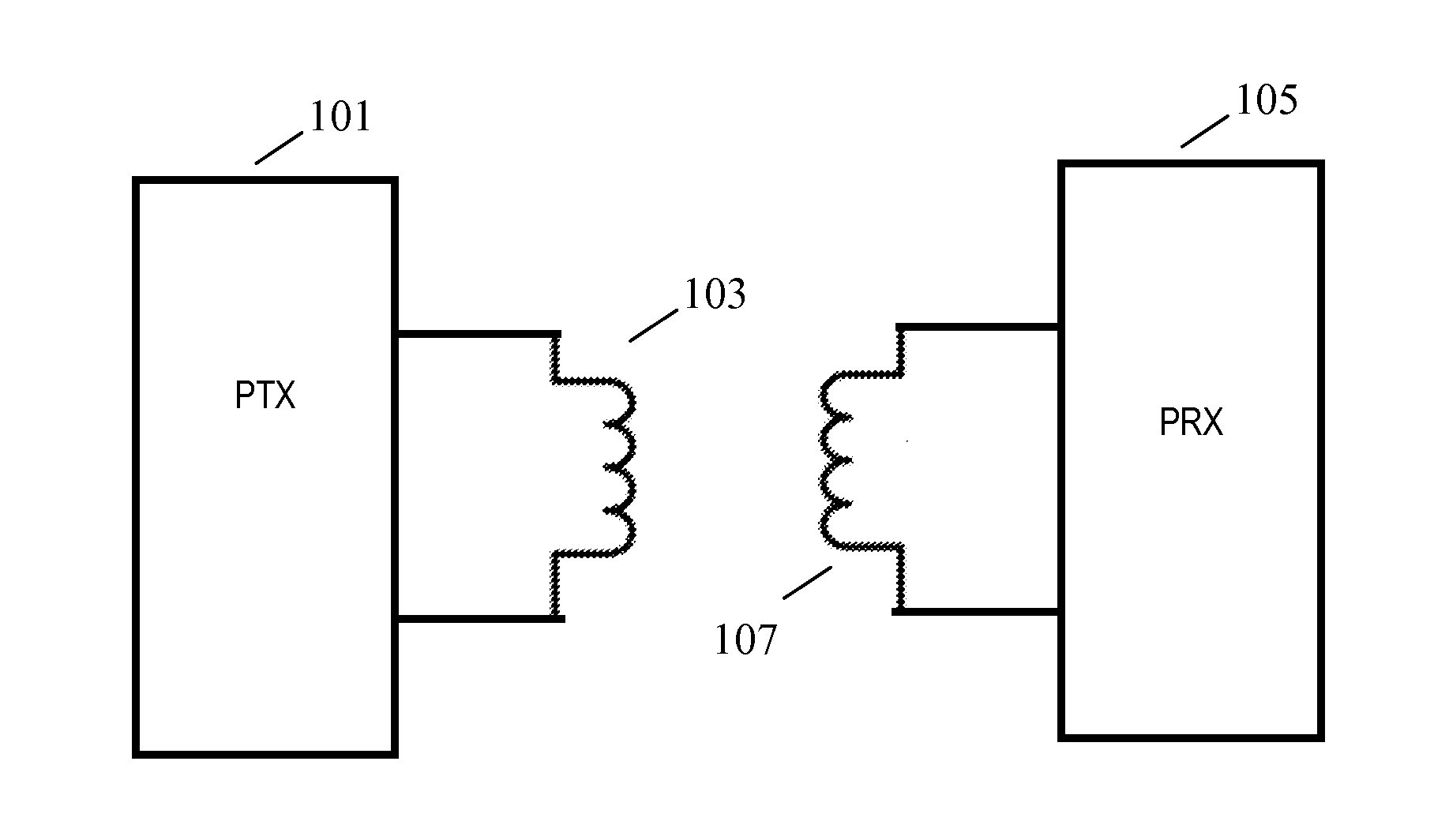
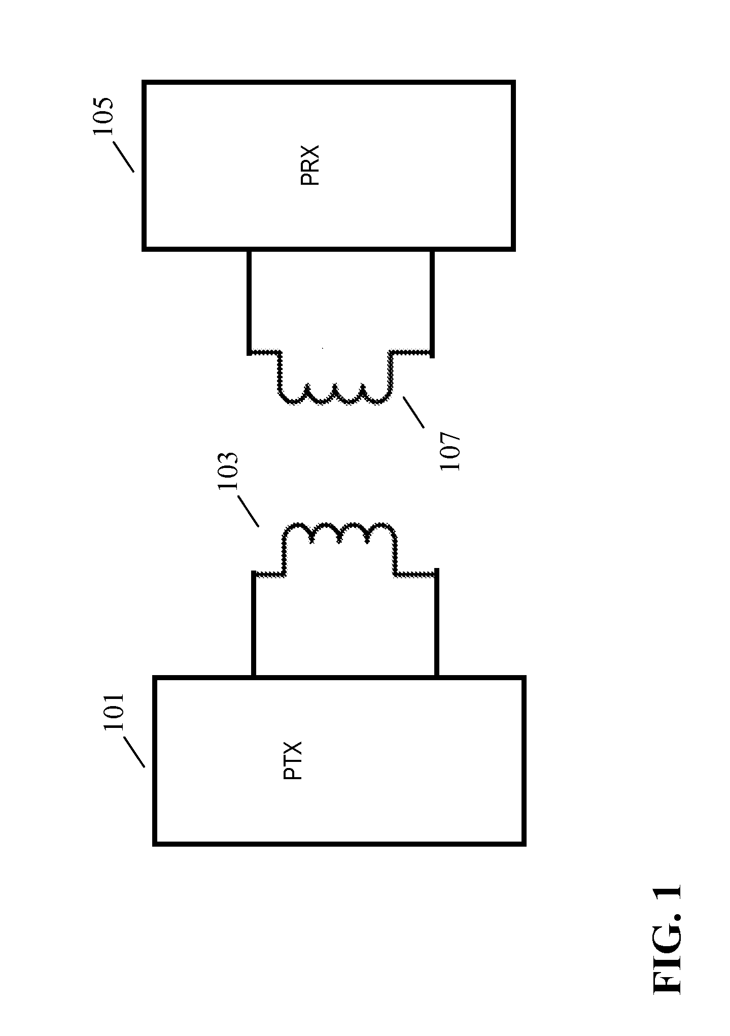
[0103]FIG. 1 illustrates an example of a power transfer system in accordance with some embodiments of the invention. The power transfer system comprises a power transmitter 101 which includes (or is coupled to) a transmitter coil / inductor 103. The system further comprises a power receiver 105 which includes (or is coupled to) a receiver coil / inductor 107.

[0104]It will be appreciate that the power receiver 105 may e.g. be a single integrated device providing both a user functionality (e.g. a communication or computational function) as well as the power transfer / extracting functionality. In other scenarios, the power receiver 105 may only comprise the functionality for extracting power with the power being provided to an external load. In the following the term power receiver 105 will be used to denote both the power transfer / extraction functionality in itself, as well as the combined functionality of the power transfer / extraction functionality and a load powered by this functionality...


PUM


Abstract

An inductive power transfer system is arranged to transfer power from a power transmitter (101) to a power receiver (103) via a wireless power signal. The system supports communication from the power transmitter (101) to the power receiver (105) based on load modulation of the power signal. The power receiver (105) transmitting (507) a first message to the power transmitter (101) which comprises a standby power signal requirement for the power signal during a standby phase. The power transmitter (101) receives (507) the message, and when the system enters the standby phase, the power transmitter (101) provides the power signal in accordance with the standby power signal requirement during. A power receiver configurable standby phase is provided which may for example allow devices to maintain battery charge or to provide fast initialization of the power transfer phase.

Description

FIELD OF THE INVENTION[0001]The invention relates to inductive power transfer and in particular, but not exclusively, to an inductive power transfer system compatible with the Qi wireless power transfer approach.BACKGROUND OF THE INVENTION[0002]The number and variety of portable and mobile devices in use have exploded in the last decade. For example, the use of mobile phones, tablets, media players etc. has become ubiquitous. Such devices are generally powered by internal batteries and the typical use scenario often requires recharging of batteries or direct wired powering of the device from an external power supply.[0003]Most present day systems require a wiring and / or explicit electrical contacts to be powered from an external power supply. However, this tends to be impractical and requires the user to physically insert connectors or otherwise establish a physical electrical contact. It also tends to be inconvenient to the user by introducing lengths of wire. Typically, power requ...

Claims


Application Information

Patent Timeline
IPC IPC(8): H02J5/00H02J7/02
CPCH02J7/025H02J5/005H04B5/0037H04B5/0093H02J7/00036H02J7/00047H02J50/80H02J50/10H02J7/00
Inventor VAN WAGENINGEN, ANDRIESSWAANS, LAURENS HENRICUS
Owner KONINKLJIJKE PHILIPS NV
Why Eureka
Try Eureka