Systems and methods for removing particulate matter from exhaust gas streams

Active Publication Date: 2015-09-10
SIDEL SYST USA
View PDF7 Cites 2 Cited by
  • Summary
  • Abstract
  • Description
  • Claims
  • Application Information

AI Technical Summary

Benefits of technology

[0031]In one embodiment, the particulate recovery system preferably includes an external modular housing constructed of sheet metal fabrication with inlet and outlet flanges for duct collection. Below the housing are hoppers from which ash and other collected material is discharged. The hoppers are desirably connected with rotary air lock valve system to prevent ingress of air into the collector. Within the housing, instead of flat plates, rappers, or electrodes, there is a rotatable drum which can have variable movement and speed and displacement depending upon volume of flue gas flow and therefore a self adjusting to any volume of flow or type of incoming particles of any size or distribution. The rotatable drum has a screen that collects particulate matter and the system is self-cleaning and powered by an external, easily accessible drive system (e.g., an electric motor). The collected particles may be dischar

Problems solved by technology

When enough dust has accumulated, the collectors are shaken to dislodge the dust, causing it to fall with the force of gravity to hopp

Method used


Image

  • Systems and methods for removing particulate matter from exhaust gas streams
  • Systems and methods for removing particulate matter from exhaust gas streams
  • Systems and methods for removing particulate matter from exhaust gas streams

Examples


Embodiment Construction

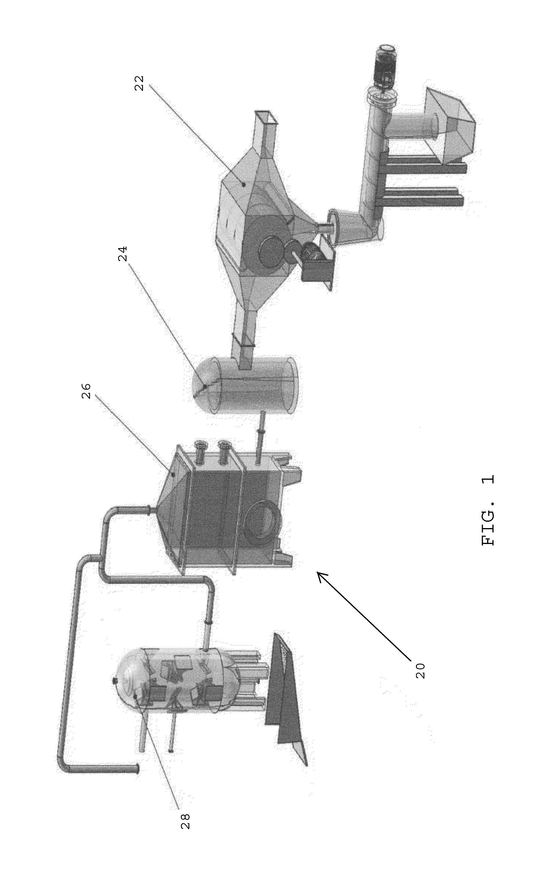
[0042]Referring to FIG. 1, in one embodiment, an exhaust gas treatment system 20 is preferably adapted to receive and treat exhaust gases from a power plant such as a coal burning power plant that produces electricity. In one embodiment, the exhaust gas treatment system 20 preferably includes a particulate recovery system 22 that removes particulate material (e.g., ash) from an exhaust gas, a sulfur gas recovery unit 24 that removes sulfur from the exhaust gas, a heat recovery unit 26 that removes heat energy from the exhaust gas, and a carbon capture unit 28 that remove carbon dioxide from the exhaust gas.

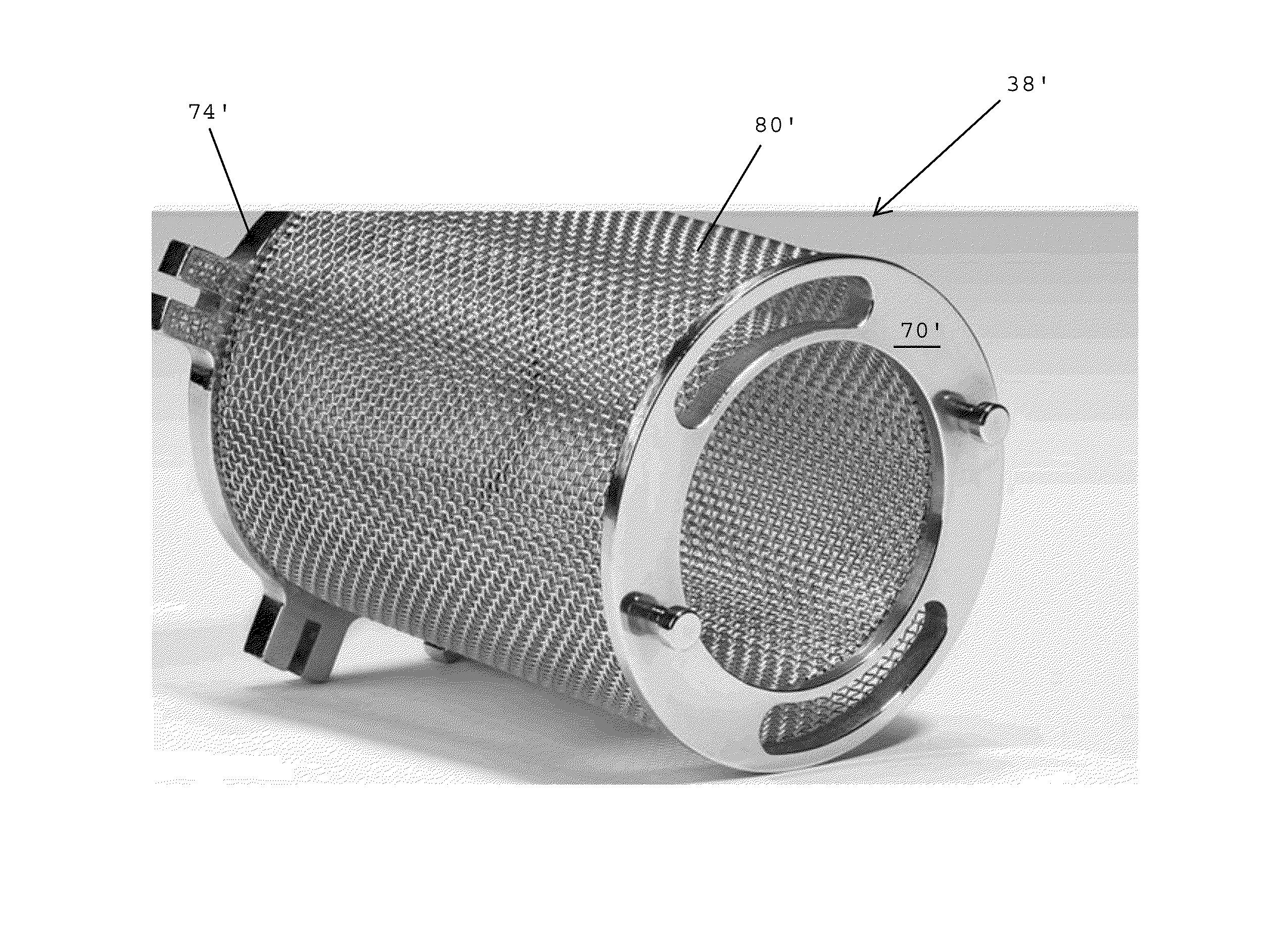
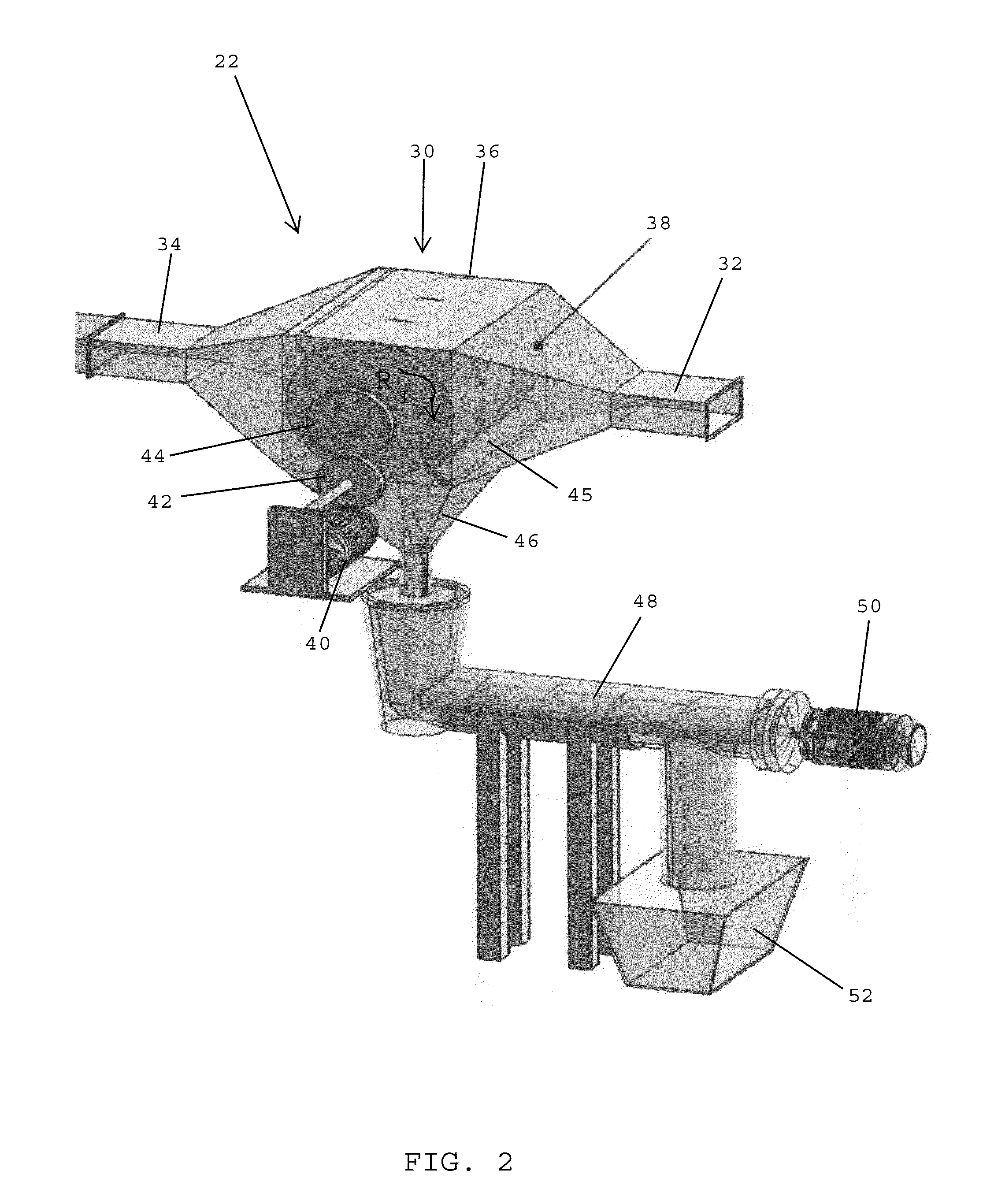
[0043]In one embodiment, the particulate recovery system 22 preferably includes a drum enclosure 30 having an inlet 32 that receives the exhaust gas of a power plant, an outlet 34 that discharges the exhaust gas from the drum enclosure after particulate matter has been removed from the exhaust gas, and a drum region 36 that contains a rotating drum 38 located between the inlet 32 ...


PUM

PropertyMeasurementUnit
Mesh sizeaaaaaaaaaa
Pressureaaaaaaaaaa
Flow rateaaaaaaaaaa

Abstract

A system for removing particulate matter from an exhaust gas includes a housing having an inlet, an outlet, and a drum region between the inlet and the outlet. A drum is rotatably mounted in the drum region of the housing and is aligned with the inlet and the outlet for intercepting the exhaust gas stream passing through the housing. The drum has a cylindrical shaped screen that allows the exhaust gas stream to pass through the drum while collecting the particulate matter present in the exhaust gas stream. As the screen rotates, a scrapper removes the particulate matter collected on the screen. A spray fixture located inside the drum sprays fluid at the inner surface of the screen to removes any particulate matter remaining on the screen after the outer surface of the screen has been scrapped.

Description

CROSS-REFERENCE TO RELATED APPLICATIONS[0001]The present patent application claims benefit of U.S. Provisional Application No. 61 / 949,278, filed Mar. 7, 2014, the disclosure of which is hereby incorporated by reference herein.BACKGROUND OF THE INVENTION[0002]1. Field of the Invention[0003]The present invention is generally directed to treating exhaust gas streams and is more particularly directed to systems and methods for removing particulate matter from exhaust gas streams.[0004]2. Description of the Related Art[0005]An electrostatic precipitator (ESP) is a large, industrial emission-control unit. An ESP is designed to trap and remove dust particles from the exhaust gas stream of an industrial process. ESPs are used in a wide variety of industries including power / electric generation, cement manufacturing, chemical manufacturing, metal manufacturing, and paper production.[0006]In many industrial plants, particulate matter created in the industrial process is carried as dust in the ...

Claims


Application Information

Patent Timeline
IPC IPC(8): B01D46/00
CPCB01D46/0065B01D46/0002B01D46/0067B01D46/0056B01D46/24B01D46/70B01D46/681B01D46/682
Inventor MUKHERJI, PARTHOSAROTHY K.
Owner SIDEL SYST USA
Why Eureka
Try Eureka