Air Vehicle and Levitation System for Air Vehicle

a technology of air vehicle and levitation system, which is applied in the field of air vehicles, can solve the problems of affecting the cooling effect of power plants, affecting the comfort of passengers, and affecting the flight of passenger aircraft, and achieves the effect of reducing energy consumption

Inactive Publication Date: 2015-09-10
AIRBUS DS
View PDF12 Cites 16 Cited by
  • Summary
  • Abstract
  • Description
  • Claims
  • Application Information

AI Technical Summary

Benefits of technology

[0028]The at least one magnetic element makes up a magnetic field generating arrangement that comprises at least one magnet, which may comprise one or more permanent magnets and/or one or more electromagnets. The provision of plural magnets is preferred, and especially electromagnets are preferred. Electromagnets have the advantage that the strength of the produced magnetic field can be adjusted and in fact individually controlled, so that the strength and configuration of the magnetic field can be adjusted or varied as a function of location along the guide path and as a function of time. Thus, for example, the magnetic field can be adapted to the weight of the air vehicle that will be landing. A

Problems solved by technology

As a result, relatively high mechanical loads are applied through the landing gear to the body of the air vehicle.
As a result, the landing, take-off and rolling stages of a flight of a passenger aircraft can sometimes be uncomfortable for the passengers.
Furthermore, due to the required high strength of the landing gear structure, it also has a relatively high weight and takes up a significant volume when retracted into the air vehicle.
This of course has negative influences on the overall energy balance, and the available payload weight and payload volume of the air vehicle.
That also causes an increased weight of the air vehicle to achieve the required strength and rigidity.
Still further, the landing gear protruding downwardly from the belly of the aircraft creates significant aerodynamic drag, and rolling along the runway creates mechanical friction, which consequently impede the take-off acceleration of the aircraft, which thus requires a longer take-off runway.
In order to make the landing gear retractable during flight to avoid the aerodynamic penalty, additional mechanical, electrical and hydraulic retraction systems and components are necessary, which further add to the weight and complexity.
However, that known system has the significant disadvantage that a highly precise control of the ground-based carriage is necessary using a highly technical control arrangement, in order to match the motion of the carriage to the motion of the approaching aircraft during the landing phase, to ensure that the aircraft is properly captured and seated onto the carriage when the aircraft lands.
Even relatively small deviations from the optimal positioning of the aircraft onto the carriage can lead to problems, or even a total no-gear landing or crash of the aircraft

Method used


Image

  • Air Vehicle and Levitation System for Air Vehicle
  • Air Vehicle and Levitation System for Air Vehicle
  • Air Vehicle and Levitation System for Air Vehicle

Examples


Embodiment Construction

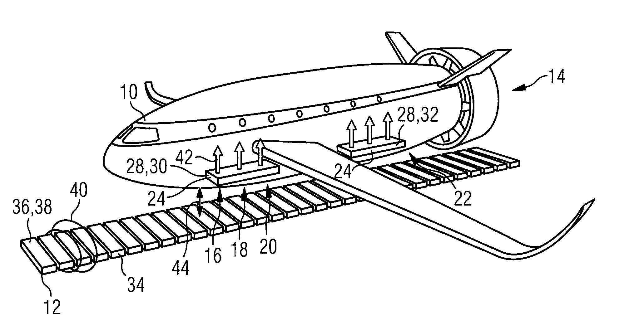
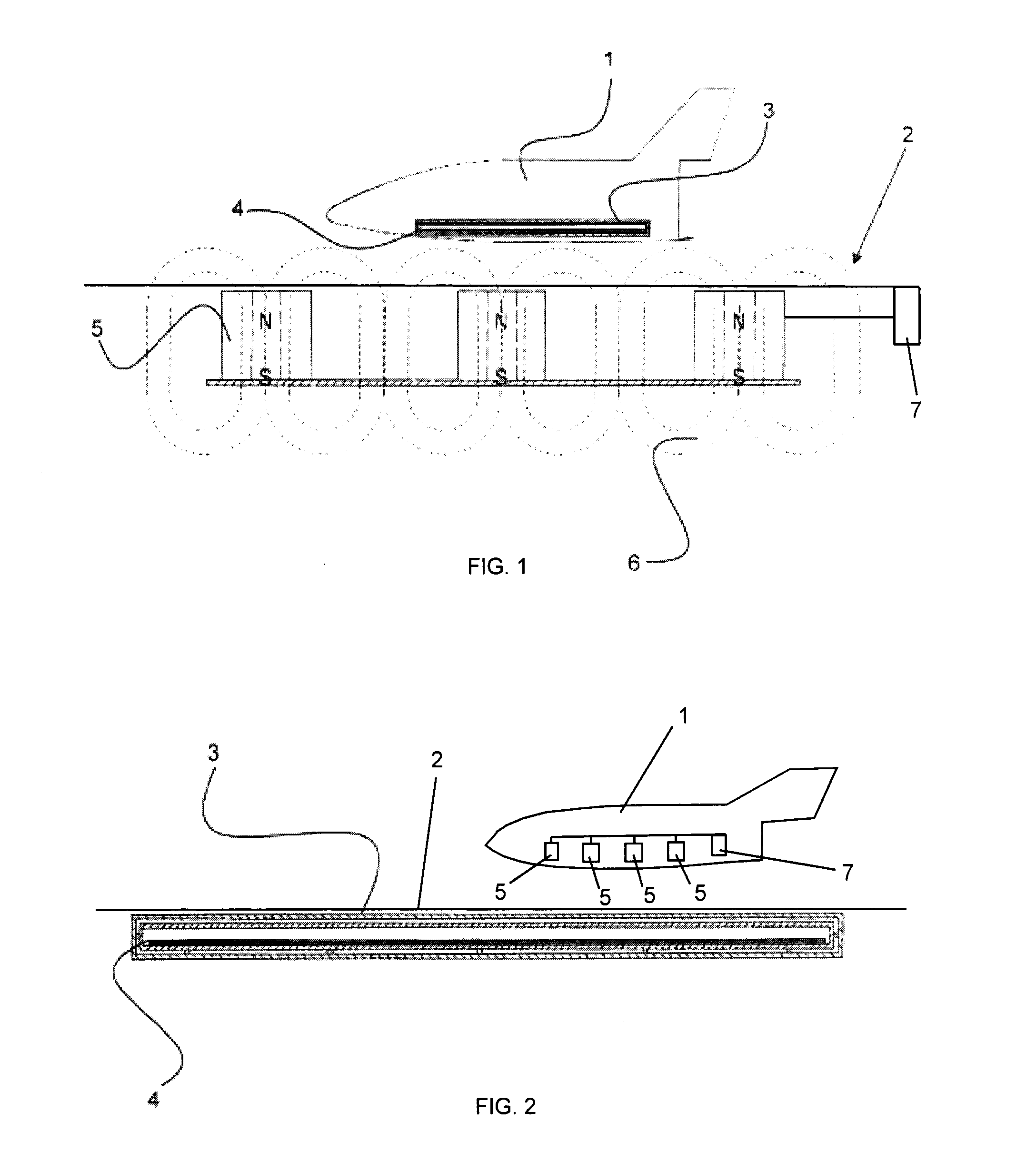
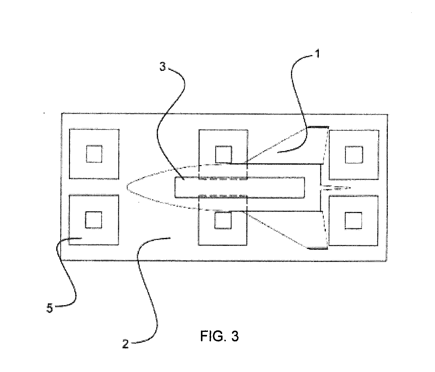
[0041]FIGS. 1 and 3 schematically illustrate a side view and a top view, respectively, of a first example embodiment of the invention involving an air vehicle 1 that is flying a landing approach above a landing and take-off runway 2. The air vehicle in this embodiment is a fixed wing aircraft that has aerodynamic lift-generating wings as well as aerodynamic control surfaces such as elevators, ailerons and a rudder (not individually shown) for aerodynamically controlling the flight of the air vehicle 1 in pitch, roll and yaw in the air, separate and independent from the runway 2. The air vehicle 1 also has thrust engines or a thrust drive system for propelling the air vehicle 1 through the air. The runway 2 is embodied or equipped as a guide path on a ground surface according to the invention.

[0042]In this embodiment, at least one superconducting element 4 is arranged in a cryostat 3 in an area along the bottom or belly of the air vehicle 1. Additionally, at least one superconducting...


PUM


Abstract

Magnetically active elements, namely magnets or superconducting elements respectively, are incorporated respectively in an air vehicle and in a guide path on which the air vehicle is to land, take-off and/or taxi. A cooling apparatus may be provided to cool the superconducting elements. The magnets may be electromagnets, and an electrical energy source and a controller are provided to energize the electromagnets in an independently controlled manner. The magnets produce a magnetic field, and the superconducting elements expel the magnetic field and cause a quantum levitation effect, by which the air vehicle is supported in a contact-free manner above the guide path. Thus, the air vehicle may omit mechanical landing gear.

Description

PRIORITY CLAIM[0001]This application is based on and claims the priority under 35 USC 119 of German Patent Application 10 2013 013 849.3 filed on Aug. 20, 2013. This application is further based on German Patent Application 10 2012 013 053.8 filed on Jul. 2, 2012. The entire disclosures of both of these German Patent Applications are incorporated herein by reference.FIELD OF THE INVENTION[0002]The invention relates to an air vehicle equipped so as to be supported above a ground surface such as a runway, taxiway or the like, as well as a system comprising such an air vehicle as well as a guide path on the ground surface by which the air vehicle can be supported and guided. The invention further relates to a method for supporting and spacing the air vehicle from the guide path.BACKGROUND INFORMATION[0003]It is conventionally known to equip an air vehicle with a landing gear including wheels on which the air vehicle is supported when it lands on, rolls along, and takes off from a groun...

Claims


Application Information

Patent Timeline
IPC IPC(8): B60L13/04B64D37/30B64D33/08B64C25/00
CPCB60L13/04B64D33/08B64D37/30B64C25/001Y02T50/80B64F1/0299
Inventor KONIGORSKI, DETLEVSTEINWANDEL, JUERGENLIEW, KAN-ERN
Owner AIRBUS DS
Why Eureka
Try Eureka