Hydraulic and electrical interface ring for a turbine engine

Active Publication Date: 2015-09-10
SN DETUDE & DE CONSTR DE MOTEURS DAVIATION S N E C M A
View PDF9 Cites 10 Cited by
  • Summary
  • Abstract
  • Description
  • Claims
  • Application Information

AI Technical Summary

Benefits of technology

[0025]Advantageously, the ring and the cylindrical bearing surface for centring the collar are designed to interact by means of sliding adjustment, that is to say with play, thereby making it possible to facilitate the mounting of the ring and to allow the dismounting thereof.
[0030]The movable part of the actuator can be fastened to an end of at least one axial position sensor, for example of the LVDT type, the opposite end of which is fastened to the interface ring. Said sensor makes it possible to recognise in real time the axial position of the movable part of the actuator (and thus the pitch of the blades of the propeller when the actuator is used to orientate the blades of the propeller). In the case of an LVDT sensor, the transformer of said sensor can be located on the side of the ring and fastened thereto. Said transformer is connected to an electric cable which can thus be connected to the connector of the ring.
[0038]Mounting the actuator and the ring on the collar can be carried out in a blind manner, that is to say without seeing said collar. The pre-mounting of the ring on the actuator makes it possible to rigidify the ancillary equipment (for example telescopic rods, LVDT sensors, etc.) between said parts during mounting and to simplify the mounting. As explained above, said mounting is relatively simple because it is sufficient for the elements of the ring to be interlocked in complementary elements of the collar to produce the assembly. The interlocking means of the ring and / or of the collar can form foolproofing means which allow correct angular positioning of the parts relative to one another. Another advantage is that the ring makes it possible to avoid carrying out complex machining operations on the collar and to transfer these operations to the ring, which has a simpler shape and smaller dimensions.

Problems solved by technology

The problem therefore arises of transferring actuating oil through the separating collar, in the present case, from the inside to the outside thereof.

Method used


Image

  • Hydraulic and electrical interface ring for a turbine engine
  • Hydraulic and electrical interface ring for a turbine engine
  • Hydraulic and electrical interface ring for a turbine engine

Examples


Embodiment Construction

[0048]In the following description, the terms “upstream” and “downstream” refer to the direction of flow of the gases in a turbine engine.

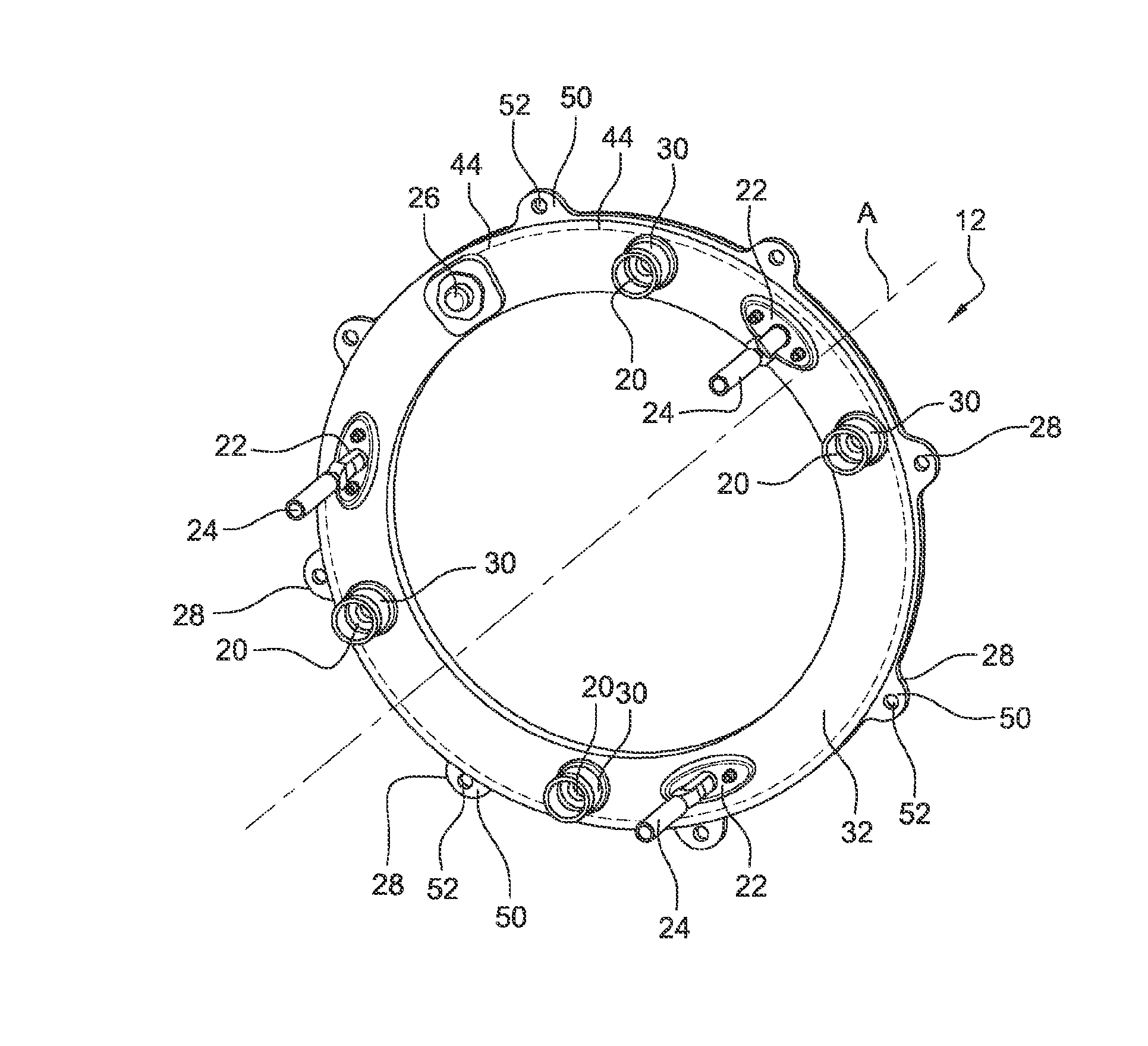
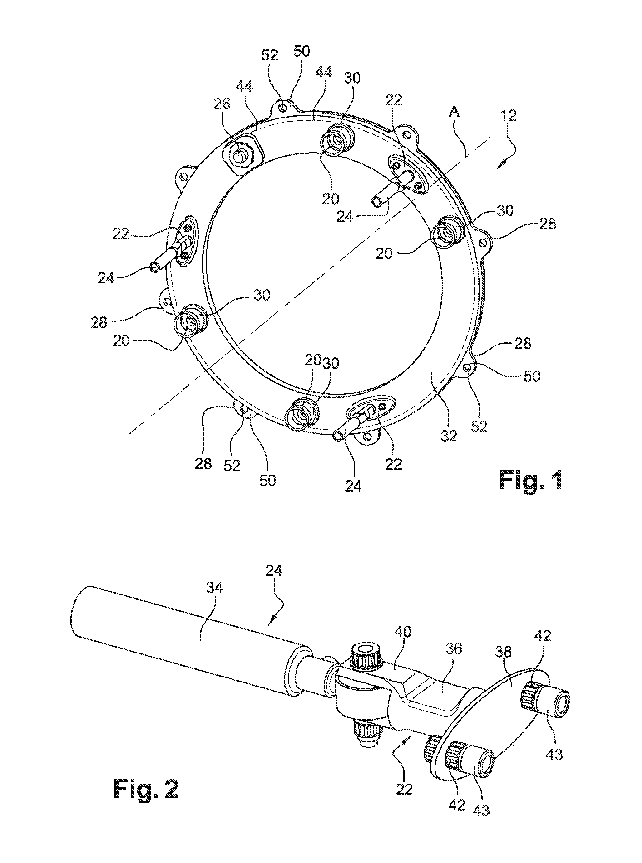
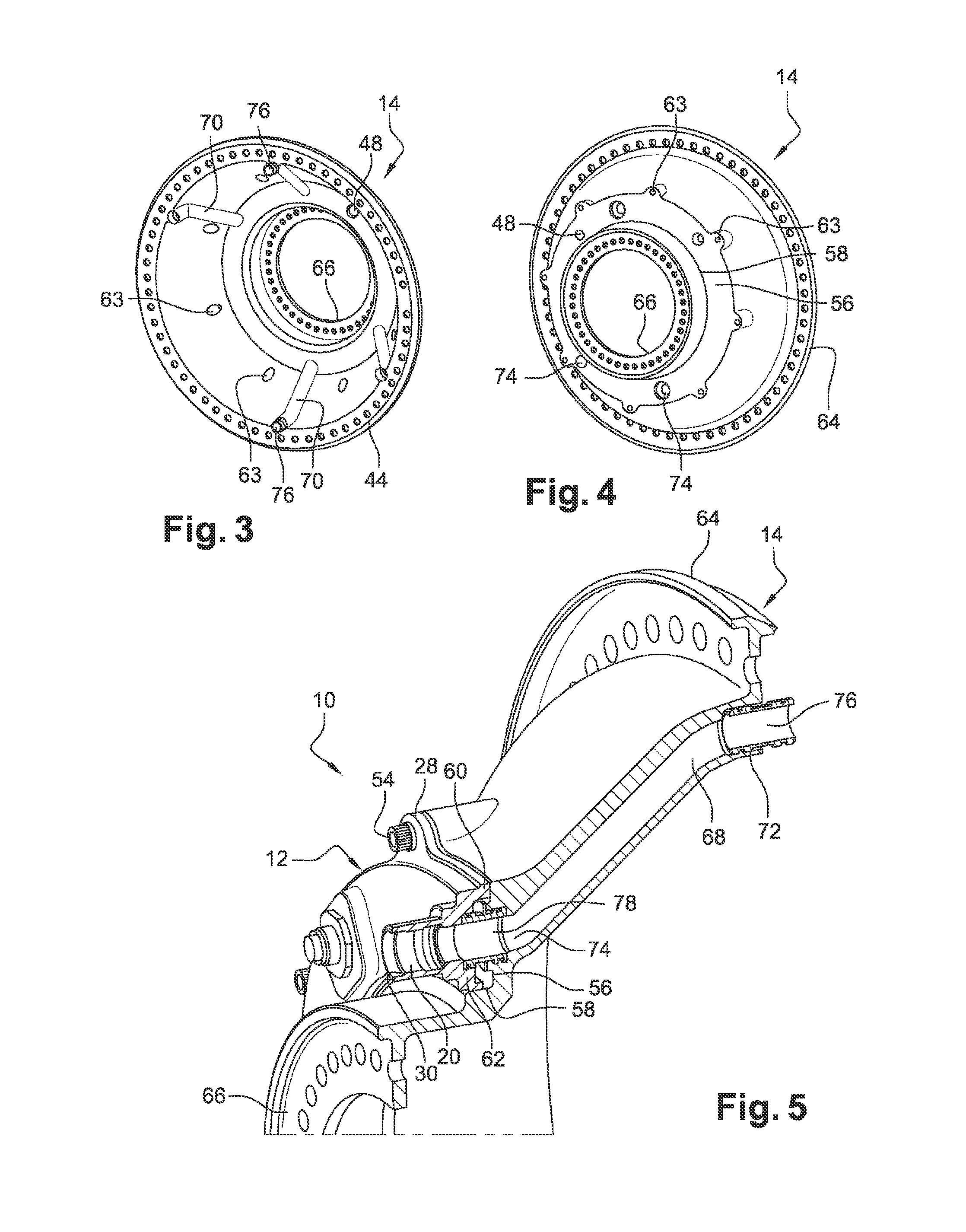
[0049]FIGS. 1 to 6 show an embodiment of an assembly 10 according to the invention, said assembly 10 which is visible in FIGS. 5 and 6 essentially comprising two members; a hydraulic and electrical interface ring 12 shown in FIG. 1 and an annular collar 14 shown in FIGS. 3 and 4. As will be described in greater detail below with reference to FIG. 7, said assembly 10 can be used to supply oil to a linear actuator 16 for setting the pitch of the blades 18 of an open-rotor type turbine engine propeller.

[0050]The ring 12 having an axis of rotation A comprises tubular ducts 20 for transferring oil, means 22 for supporting LVDT sensors 24, a connector 26 for electrical connection of said sensors 24, and means 28 for fastening to the collar 14.

[0051]The ducts 20 are substantially parallel to one another and to the axis A, and there are at least four ther...


PUM

PropertyMeasurementUnit
electricalaaaaaaaaaa
pitch angleaaaaaaaaaa
pressureaaaaaaaaaa

Abstract

The disclosed subject matter relates to a hydraulic and electrical interface ring for a turbine engine, characterized in that said ring comprises fluid transfer pipes which axially pass therethrough and having axial ends that form axial interlocking means, the supporting means of at least one electrical device, and at least one electrical linking connector of the device, said connector being configured to engage by axial interlocking with a complementary electrical connector of another part.

Description

TECHNICAL FIELD[0001]The present invention relates to a hydraulic and electrical interface ring for a turbine engine, which is particularly suitable but not exclusively for supplying fluid (such as oil) to an open-rotor type linear turbine engine actuator.PRIOR ART[0002]An open-rotor type turbine engine mainly comprises, along a longitudinal axis and inside a cylindrical nacelle, supported by the structure of the aircraft (such as the rear portion of the fuselage of an aeroplane), a “gas generator” part and a “thruster” part (only the nacelle part covering the gas generator is fixed, whereas the nacelle parts in which the rotating casings are accommodated are rotational). The thruster part comprises two coaxial and counter-rotating propellers, which are upstream (front) and downstream (rear) respectively and comprise rotational casings having polygonal rings, and which propellers are set into opposite rotation from one another, for example, by a suitable mechanism which is driven by...

Claims


Application Information

Patent Timeline
Patent Type & Authority Applications(United States)
IPC IPC(8): F01D25/18F16C33/66
CPCF16C33/6677F01D25/18F16N21/00F01D7/00F05D2220/325F05D2260/76F05D2260/57F05D2260/70F16C2360/23B64C11/38Y10T29/49826Y02T50/60
Inventor CURLIER, AUGUSTINBELMONTE, OLIVIER
Owner SN DETUDE & DE CONSTR DE MOTEURS DAVIATION S N E C M A
Why Eureka
Try Eureka