Indicator Device

a technology of indicator device and indicator, which is applied in the direction of gas detection, material testing goods, chemical methods analysis, etc., can solve the problems of not being able to print, not being able to apply such indicators in the reduced form, and being sensitive to oxygen, so as to achieve the effect of reducing the passage of atmospheric agents

Active Publication Date: 2015-09-10
INSIGNIA TECH
View PDF8 Cites 19 Cited by
  • Summary
  • Abstract
  • Description
  • Claims
  • Application Information

AI Technical Summary

Benefits of technology

[0098]The semi-permeable barrier layer may be configured t

Problems solved by technology

However, the indicator disclosed is necessarily sensitive to oxygen.
In addition, it is unclear as to how such an indicator may be applied in the reduced form in atmospheric conditions.
Also, there is no indication regarding how such an indicator might be incorporated into a multi-layered product.
Furthermore, the redox active species can leach out of solution following storage under ambient conditions, meaning that a solution of the composition is not suitable for use in printing.
The inks and indicator compositions described in WO 03/021252 are therefore not suitable for use in many modern day printing processes, which require the use of organic solvent based inks, or in the application to many types of modern packaging, which require that the compositions are stable (i.e., resistant to leaching) on exposure to water.
Furthermore, it can be impractical to activate indicator compositions (incorporated into inks) after they have been printed and sealed on a substrate, such as packaging.
For example, it can be difficult to expose the printed indicator composition to the correct amoun

Method used

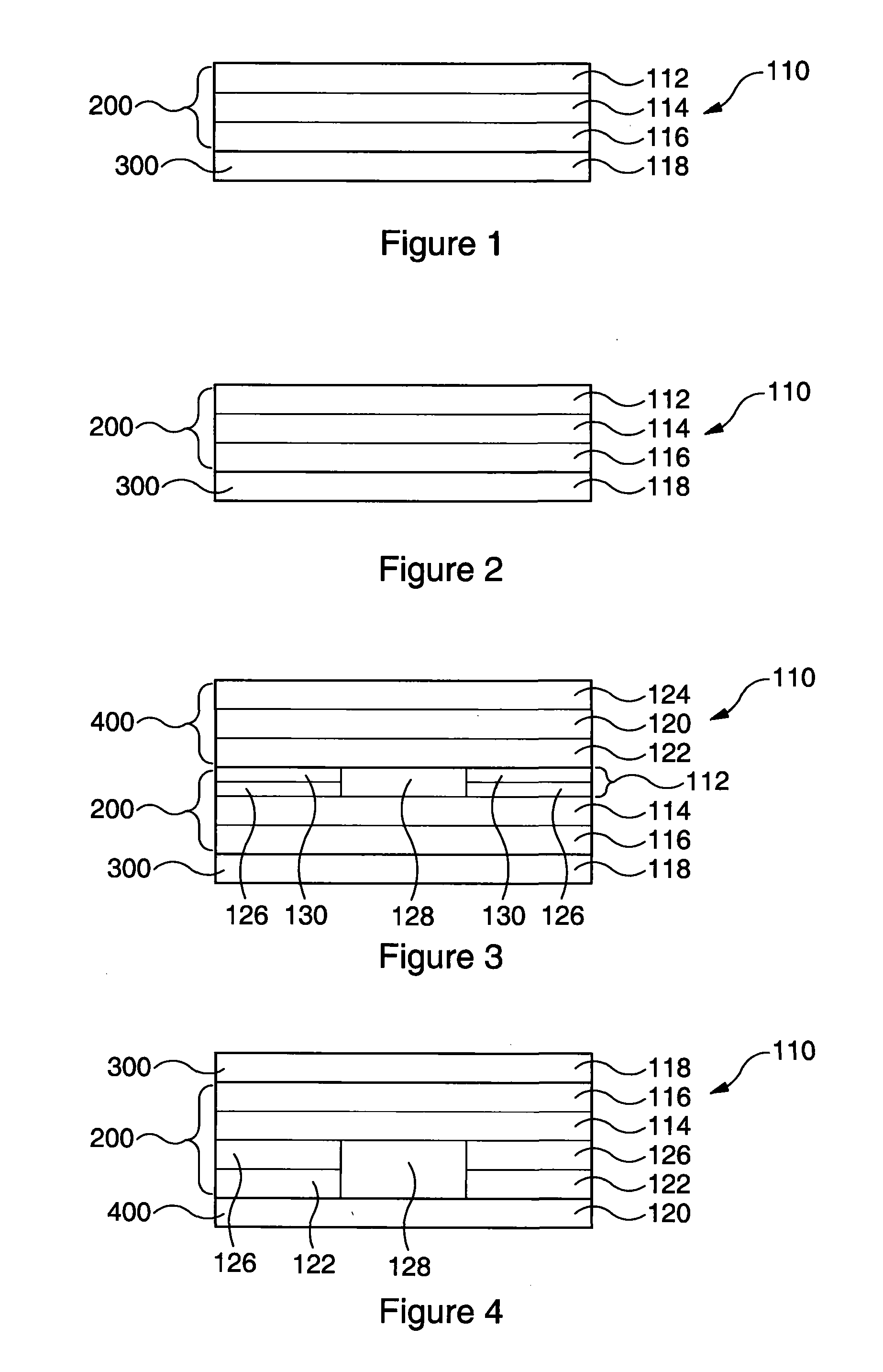
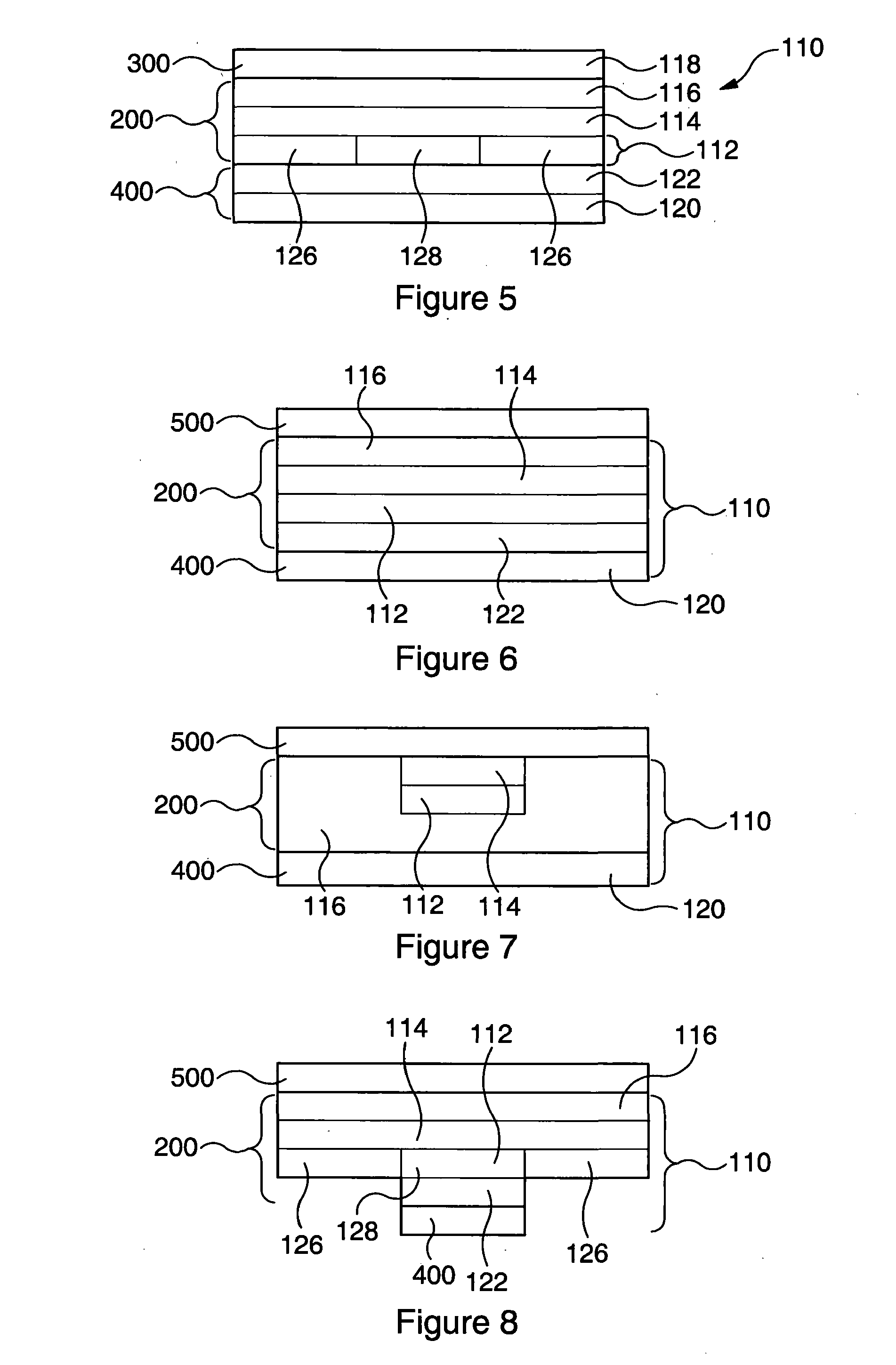
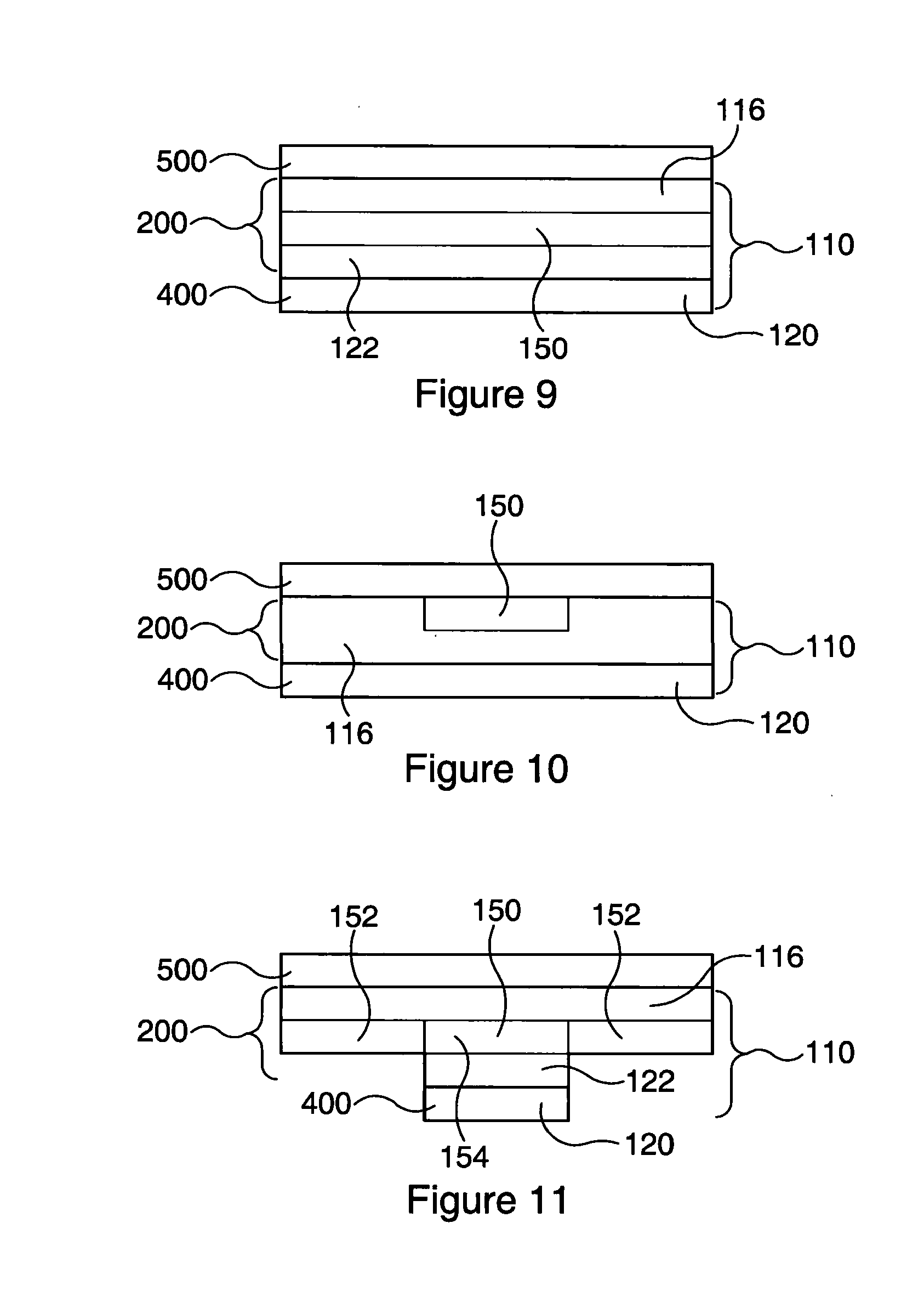

Image

  • Indicator Device
  • Indicator Device
  • Indicator Device

Examples


example 1

Polypropylene Substrate

[0361]

TABLE 1.1Recovery at room temperatureTime (days)L*(D65)a*(D65)b*(D65)193.27−2.65−0.89289.06−10.48−6.18385.81−14.21−9.27683.10−16.17−12.00782.27−16.61−12.31882.04−16.23−11.93

TABLE 1.2Recovery in refrigeratorTime (days)L*(D65)a*(D65)b*(D65)193.27−2.65−0.89292.21−5.83−1.83390.21−9.46−4.88685.16−15.43−10.80783.70−16.33−12.32883.50−16.42−12.48

TABLE 1.3Control / reference in refrigeratorTime (days)L*(D65)a*(D65)b*(D65)193.27−2.65−0.89293.52−1.740.07392.59−2.28−0.14693.65−2.080.29793.82−2.260.43893.72−1.890.20

example 2

Platinised Polypropylene Substrate

[0362]

TABLE 2.1Recovery at room temperatureTime (days)L*(D65)a*(D65)b*(D65)192.25−3.73−0.78286.72−12.85−7.14384.57−15.47−9.99681.05−17.85−13.91780.65−18.07−14.15880.33−17.87−14.53

TABLE 2.2Recovery in refrigeratorTime (days)L*(D65)a*(D65)b*(D65)192.25−3.73−0.78290.27−6.30−2.84388.03−10.43−6.54684.59−15.23−10.66781.97−16.94−13.35882.23−17.05−13.54

TABLE 2.3Control / reference in refrigeratorTime (days)L*(D65)a*(D65)b*(D65)192.25−3.73−0.78292.29−4.230.61391.15−3.94−0.57692.32−3.20−0.30792.03−4.780.44892.10−4.310.07

example 3

Aluminium Oxide Foil Substrate

[0363]

TABLE 3.1Recovery at room temperatureTime (days)L*(D65)a*(D65)b*(D65)185.21−1.53−1.17280.51−11.02−7.57377.83−14.71−10.71674.58−17.11−13.41774.48−16.29−13.05874.43−16.17−12.94

TABLE 3.2Recovery in refrigeratorTime (days)L*(D65)a*(D65)b*(D65)185.21−1.53−1.17284.18−4.31−2.80382.03−8.27−4.83678.26−14.44−10.14777.20−15.68−11.77876.21−16.10−12.62

TABLE 3.3Control / reference in refrigeratorTime (days)L*(D65)a*(D65)b*(D65)185.21−1.53−1.17285.01−2.10−1.32385.23−1.43−1.19685.13−1.59−1.41785.01−2.04−1.38885.16−1.51−1.31


PUM


Abstract

There is described an indicator device for detecting a change in atmospheric conditions, the indicator device comprising an indicator section and a barrier section adjacent thereto, said indicator section comprising: an indicator material; a substrate material; and a first adhesive layer; the indicator material and the substrate material being incorporated into one or more layers; wherein the indicator material displays different visible properties in different atmospheric conditions, and wherein the barrier section provides a semi-permeable seal configured to allow controlled flow to the indicator of an atmospheric agent that effects a change in visible properties of the indicator material. There is also described a method for preparing an indicator device, and products derived therefrom. The indicator device may be used to detect oxygen, water, carbon dioxide, an amine and/or ammonia, or to indicate the passage of time.

Description

FIELD OF INVENTION[0001]The present invention relates to an indicator device a method for preparing an indicator device, and products derived therefrom. In particular, the present invention relates to a laminated indicator device comprising an oxygen and / or water sensitive, carbon dioxide sensitive or an amine and / or ammonia sensitive ink which can be activated using, for example, UV light, a reducing agent or carbon dioxide. The products derived therefrom may include, for example, a multilayer adhesive tape or sticker, which can be used to detect oxidising agents, oxygen, water, reducing agents, UV light, carbon dioxide, amines, ammonia, temperature and the passage of time. A further example of the use of the indicator device is as a time-temperature history indicator.[0002]Perishable goods, and in particular drinks and foodstuffs, are often provided in some form of air-tight packaging. This packing can be applied in a modified atmosphere (known as modified atmosphere packaging (MA...

Claims


Application Information

Patent Timeline
IPC IPC(8): G01N21/77
CPCG01N21/77G01N31/225
Inventor SMYTH, ERIKSKINNER, GRAHAM ALEXANDERALLAN, DEBORAH
Owner INSIGNIA TECH
Why Eureka
Try Eureka