
Device and method for reducing pain

a technology for reducing pain and pain, applied in the field of devices for reducing pain, can solve the problems of increasing pain perception on the one hand, unpredictable severe pain may occur with minimally invasive medical procedures, and anxiety bordering on panic, so as to reduce pain and reduce pain

Inactive Publication Date: 2015-09-17
MUCKE MARTIN +2
View PDF14 Cites 47 Cited by
  • Summary
  • Abstract
  • Description
  • Claims
  • Application Information

AI Technical Summary

Benefits of technology

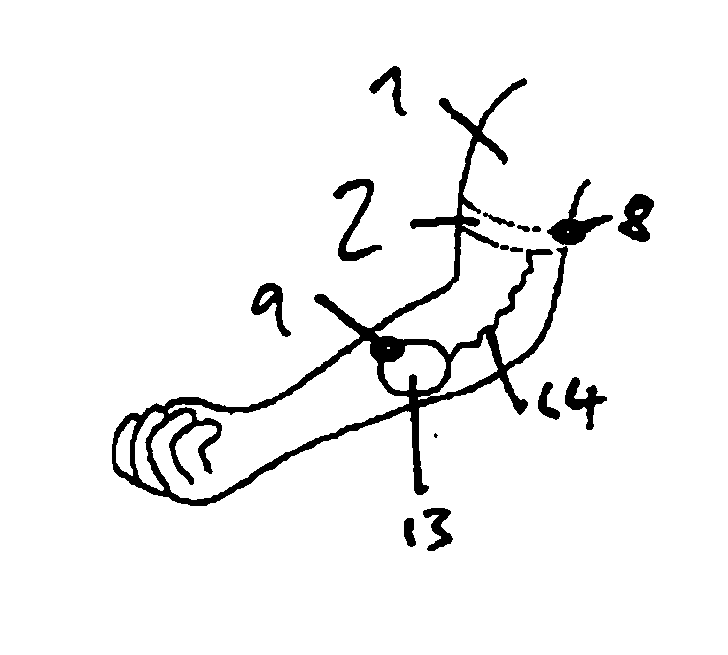
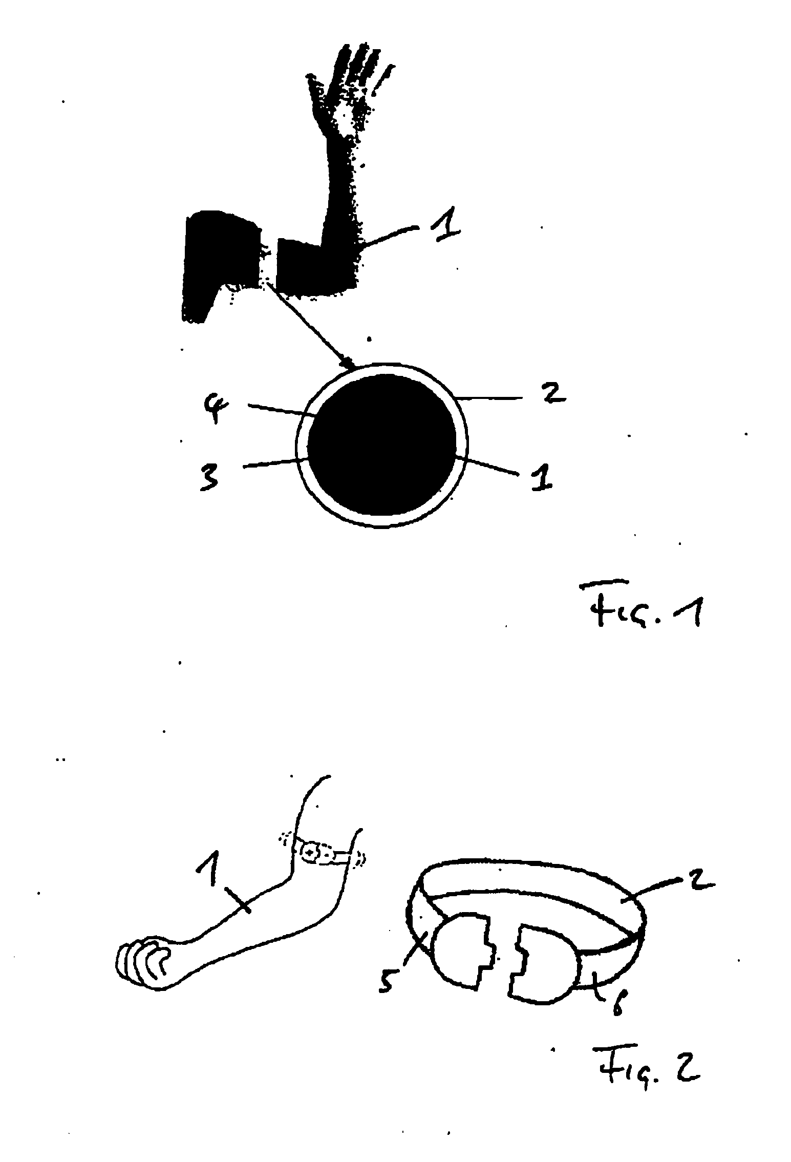
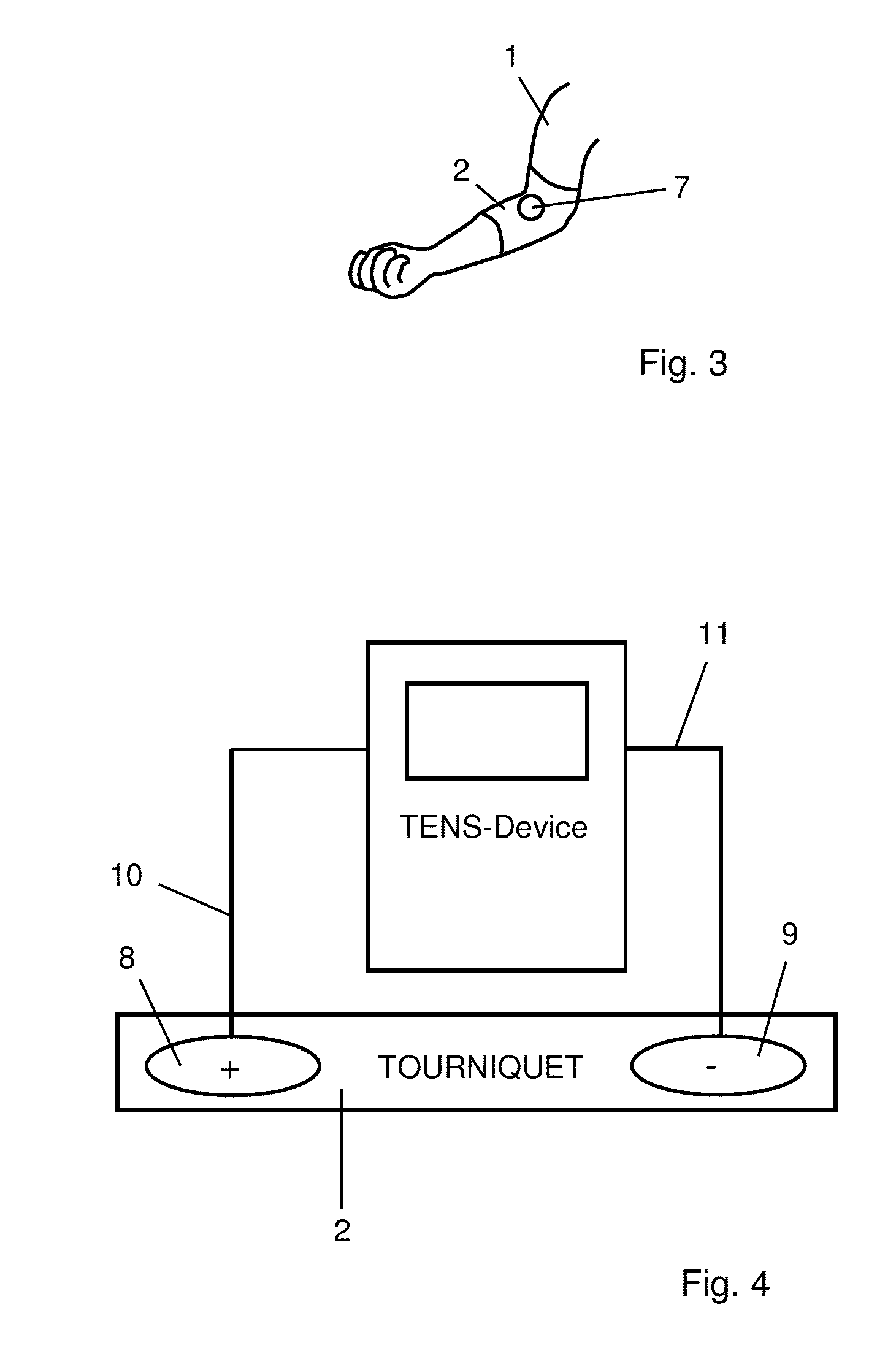
The object of this invention is to create a better device to help reduce pain in humans or animals when getting shots, receiving infusions, or having blood samples taken. This device should help make injections and punctures less painful.

Problems solved by technology

The preparatory measures and the pain caused by the needle puncture are often associated with a stress reaction (distress).
In children in particular, unpredictable severe pain may occur with minimally invasive medical procedures, for example, venous punctures, intramuscular injections or when administering infusions.
These procedures may therefore cause anxiety and stress reactions in both the child and the parent, which can result in an increased perception of pain on the one hand, and problems in performing the procedure on the other hand.
Since pain is a personal experience which some people perceive more strongly and others more weakly, this pain may even cause some people to react to this experience of pain with an anxiety bordering on panic.
All these methods and processes are complex in terms of resources because they require time and personnel and accordingly, are cost-intensive.
However, this method does not make it possible to sample larger volumes of blood such as those often needed in clinical diagnostic procedures.
Furthermore, the device described in US 2005 / 0038463 does not allow therapeutic administration of vaccines or infusions, for example.
However, the embodiments described here do not include a tourniquet for reducing the venous blood flow, which is why they have only limited suitability for collecting blood.
These skin nociceptors are excited by harmful stimuli such as puncturing with a cannulated needle to collect blood through the skin and vascular tissue (intima, media, adventitia), for example, and they cause the perception of pain.
It has been found that for achieving or triggering an LTD, the TENS may not be sufficient.

Method used


Image

  • Device and method for reducing pain
  • Device and method for reducing pain
  • Device and method for reducing pain

Examples


first example

[0134]Investigation of the effect of pain suppression according to the invention on various pain modalities by means of quantitative sensory testing (QST)

[0135]This study shows that use of the electrodes according to the invention leads to an increase in the pain threshold when experiencing pain. This may cause a long-term depression (LED) of the synaptic transmission due to low-frequency electrical stimulation.

Method

[0136]On the basis of a protocol for quantitative sensory testing (QST, Rolke, R., Magerl, W., Campbell, K. A. et al., 2006, Quantitative sensory testing: a comprehensive protocol of clinical trials, European Journal of Pain, Vol. 10(1), pages 77-88; Rolke, R., Baron, R., Maier, C., et al., 2006, Quantitative sensory testing in the German Neuropathic Pain Research Network (DFNS): Standardized protocol and reference values, PAIN, Vol. 123(3), pages 231-243; Backonja, M. M., Walk, D., Edwards, R. R., Sehgal, N., Moeller-Bertram, T., Wasan, A., Irving, G., Argoff, C., Wall...

second example

[0146]In a second experimental series the function pattern that was developed (bandage with spiny electrode) (see FIGS. 17 and 18) was tested in pressure pain on the knee.

[0147]For the test procedure a hand-held algometer (Somedic AB, Sweden) was used. The probe tip (1 cm2) was tested on three predetermined skin points in the peripatellar region (see FIG. 19). The pressure was applied at the rate of 30 kPa / s until the test subject reported that the pressure was perceived as painful.

[0148]Six people were tested with the following sequence pattern:[0149]Each person was tested a total of 6 days of three passes each at the Bonn University Clinic (6×3=18 passes)[0150]Days 1 and 2 were performed without stimulation (baseline)[0151]Days 3 and 4 were performed with sham (sham)[0152]Days 5 and 6 were performed with the function pattern (including the electrode assembly)[0153]Each stimulation lasted 15 minutes (effective stimulation pattern: see first example) and was repeated after 45 minute...

third example

[0162]The electrode assembly is identical to the electrode assembly in the second experimental series (flat electrode assembly in an array). In addition, a vibration motor that would set the electrode assembly in vibration and was connected to the electrode assembly was used. A PicoVibe™ motor 4 mm vibration motor, 8 mm type according to Data Sheet 304-008 from Precision Microdrives™ was used as the vibration motor.

[0163]The experimental series with five test subjects showed a further increase in the pain threshold after a stimulation period of 5 minutes in comparison with the first experimental series. The additional vibration thus led to a further reduction in pain and / or pain suppression.


PUM


Abstract

The invention relates to a device and a method for reducing pain on a human or animal body using at least two electrodes as part of an electrode assembly. The device includes an electrode assembly, the surface of which can be brought into contact with the surface of a human or animal body, a pulse generating unit for applying current to the electrode assembly, and a vibration unit for vibration of the electrode assembly.

Description

REFERENCE TO RELATED APPLICATIONS[0001]This application is the national stage application under 35 U.S.C. §371 of the International Application No. PCT / EP2012 / 000706 filed Feb. 17, 2012, which claims the benefit of German Patent Application No. 102011120068.5, filed Dec. 5, 2011, and German Patent Application No. 102011011610.9, filed Feb. 17, 2011, the entire disclosures of which are incorporated herein by reference in their entireties for all purposes.FIELD OF THE INVENTION[0002]The invention relates to a device for reducing pain in medical procedures on a human or animal body part, said device having a vessel through which a fluid flows, in particular blood.BACKGROUND OF THE INVENTION[0003]In medical diagnostics, millions of vaccinations, infusions, venous punctures, transfusions and blood samples are performed and taken each day. These medical procedures on a human or animal body must be performed rapidly because of the large number of procedures, if for no other reason.[0004]Wi...

Claims


Application Information

Patent Timeline
IPC IPC(8): A61H23/02A61H23/00A61B5/15
CPCA61H23/02A61B5/150137A61H2201/10A61H23/00A61B5/150106A61B17/1322A61N1/0456A61N1/0476A61N1/0484A61N1/36021A61H11/00A61H23/0263A61H2201/1635A61H2201/165A61H2201/5007A61H2201/5035A61H2201/5097A61H2205/06A61H2230/655
Inventor MUCKE, MARTINWEIGL, TOBIASWEIGL, JOHANNES
Owner MUCKE MARTIN
Learn More