
Vehicle energy-management device

a technology for energy management and hybrid vehicles, applied in the direction of vehicle position/course/altitude control, process and machine control, instruments, etc., can solve the problems of increasing the computation load applied to the controlling device of the hybrid vehicle, the error between the predicted value and the actual measured value of the amount of energy consumption, and the increase of the number of sections. , to achieve the effect of suppressing computation load and high energy efficiency

Active Publication Date: 2015-09-17
MITSUBISHI ELECTRIC CORP
View PDF6 Cites 6 Cited by
  • Summary
  • Abstract
  • Description
  • Claims
  • Application Information

AI Technical Summary

Benefits of technology

The present invention is a vehicle energy-management device that creates a control plan for the vehicle that is efficient in energy usage and reduces computation loads. The device analyzes the travel route in detail to plan the specifics of controlling the vehicle's apparatuses. This reduces errors and accumulation of errors up to the latter half of the travel route, resulting in less replanning and reduced computation loads. The device also revises the plan for the sections that are finely divided from the point of replanning, increasing the accuracy of control and reducing fuel consumption. This reduces the cost of the controller by using low-priced microcomputers or memories.

Problems solved by technology

Even if a travel route to the destination is divided into a plurality of sections and a control plan for the hybrid vehicle is prepared based on the predicted value of the amount of energy consumption in each section, changes in the actual traveling conditions cause an error between the predicted value and the actually measured value of the amount of energy consumption.
The original control plan becomes inappropriate due to the accumulation of errors during traveling, whereby the control plan needs to be revised (replanned).
However, frequent replanning increases the computation loads applied to the controlling device of the hybrid vehicle.
In particular, the number of sections increases with increasing distance or travel time to the destination, whereby massive amounts of calculation are required to create the control plan, taking more time to create and replan the control plan.

Method used


Image

  • Vehicle energy-management device
  • Vehicle energy-management device
  • Vehicle energy-management device

Examples


Embodiment Construction

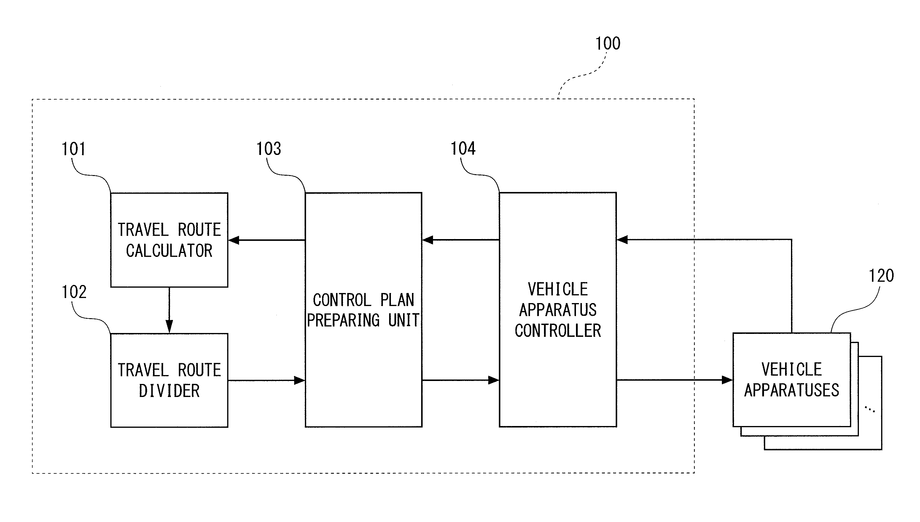
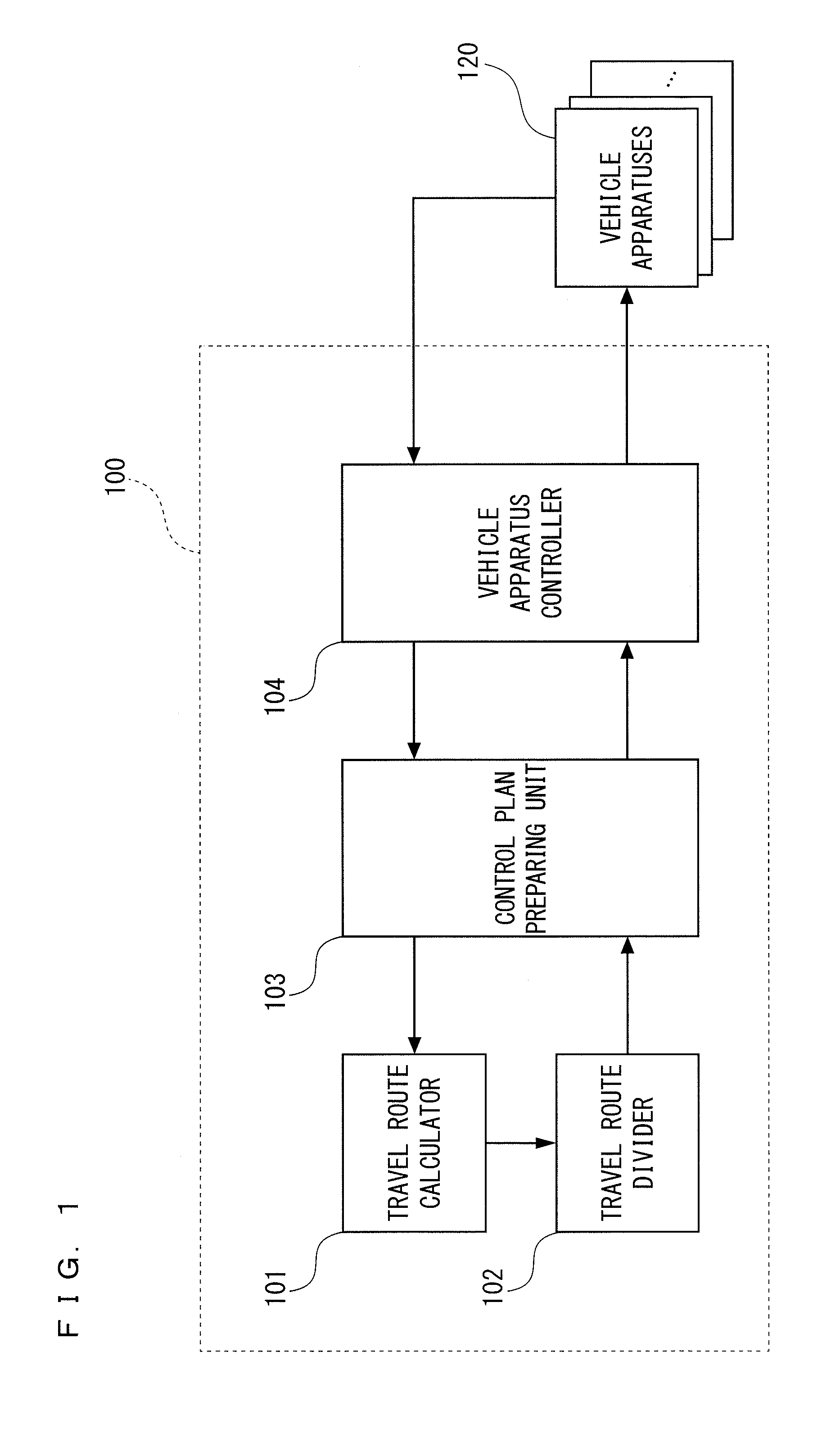
[0017]FIG. 1 is a block diagram showing a configuration of a vehicle energy-management device according to a preferred embodiment of the present invention. Although the vehicle energy-management device according to the present invention is broadly applicable to the vehicles including more than one energy source, this preferred embodiment refers to the vehicle energy-management device mounted onto a vehicle that is powered by two power sources of fuel energy and electric energy.

[0018]A vehicle energy-management device 100 controls vehicle apparatuses 120 such as a motor, an engine, and a generator of a vehicle (hereinafter also referred to as “own vehicle”) including the vehicle energy-management device 100 mounted thereon. The motor is capable of functioning as an electric generator (regenerative brake) that regenerates electric power during deceleration of the vehicle. The vehicle apparatuses 120 controlled by the vehicle energy-management device 100 may include apparatuses, such a...


PUM


Abstract

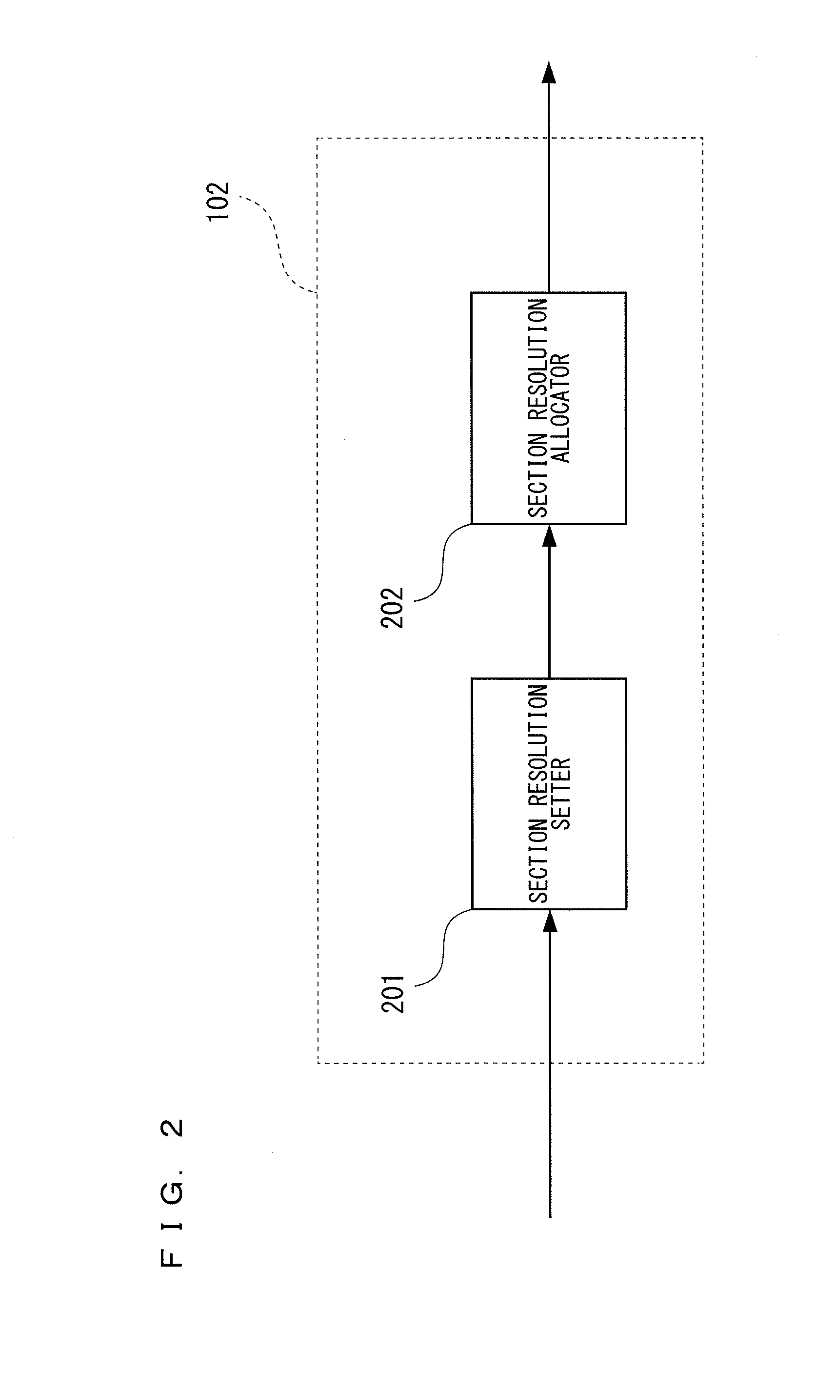
A vehicle energy-management device is used for a vehicle that is equipped with a plurality of vehicle apparatuses driven by different energy sources. The vehicle energy-management device includes a travel route calculator that calculates a travel route of the vehicle, a travel route divider that divides the travel route into a plurality of sections, a control plan preparing unit that prepares, for each of the plurality of sections, a control plan for the plurality of vehicle apparatuses, and a vehicle apparatus controller that controls the plurality of vehicle apparatuses according to the control plan. The travel route divider determines a length of each of the sections such that a resolution is higher for a section closer to the vehicle and divides the travel route.

Description

BACKGROUND OF THE INVENTION[0001]1. Field of the Invention[0002]The present invention relates to a vehicle energy-management device that controls energy consumption of a vehicle including a plurality of different energy sources and, in particular, to a method for dividing a route to plan control on an engine and a motor.[0003]2. Description of the Background Art[0004]The so-called hybrid vehicles, which are powered by a plurality of different energy sources such as fuel energy and electric energy, have various operation modes to suppress the amount of energy consumption. The operation modes of the hybrid vehicle are, for example, the traveling mode in which the vehicle is only powered by the engine, the traveling mode in which the vehicle is only powered by the motor, the traveling mode in which the vehicle is powered by the combination of the engine and the motor, and the mode in which the engine generates electric power and the generated electric power is accumulated and used to d...

Claims


Application Information

Patent Timeline
Patent Type & Authority Applications(United States)
IPC IPC(8): B60W20/00B60W10/08B60W10/26B60W10/06B60L50/16
CPCB60W20/104B60W10/06B60W10/08B60W10/26B60W2510/06B60W2710/248B60W2510/244B60W2550/142B60W2560/02B60W2710/06B60W2710/08B60W2510/08B60W2710/242B60W2552/00B60W2552/15B60W2530/209B60W50/0097B60W20/12B60W2556/50Y02T10/62Y02T10/7072Y02T90/16
Inventor MATSUNAGA, TAKANORI
Owner MITSUBISHI ELECTRIC CORP
Learn More