
Mirco-electro-mechanical system pressure sensor and manufacturing method thereof

a technology of micro-electro-mechanical and pressure sensor, which is applied in the direction of fluid pressure measurement, fluid pressure measurement by electric/magnetic elements, instruments, etc., can solve the problems of deviating from the design value, inaccurate sensing results, and internal pressure of enclosed spa

Inactive Publication Date: 2015-09-17
RICHTEK TECH
View PDF15 Cites 24 Cited by
  • Summary
  • Abstract
  • Description
  • Claims
  • Application Information

AI Technical Summary

Benefits of technology

The present invention provides a MEMS pressure sensor with a semi-open chamber and a cap that form an enclosed space with the membrane. The top and bottom electrodes form a sensing capacitor to sense the external pressure. The sensor can be connected to a reference pressure source through a connection passage. The membrane and insulating layer are bonded through an insulating layer, and the cap and membrane are bonded through an insulating layer. The membrane includes a conductive metal layer to form a lower electrode and a mass. The sensor also includes obstacles at the opening of the semi-open chamber and a plurality of stoppers at the cap. The manufacturing method involves forming layers, conducting plugs, and a cap to form the enclosed space with the membrane. The technical effects of the invention include improved accuracy and reliability of pressure sensing and simplified manufacturing process.

Problems solved by technology

Such residual gas will be released (outgas) to the enclosed space 12, causing the internal pressure of the enclosed space 12 to deviate from the design value such that the sensing result is inaccurate.

Method used


Image

  • Mirco-electro-mechanical system pressure sensor and manufacturing method thereof
  • Mirco-electro-mechanical system pressure sensor and manufacturing method thereof
  • Mirco-electro-mechanical system pressure sensor and manufacturing method thereof

Examples


Embodiment Construction

[0030]The drawings as referred to throughout the description of the present invention are for illustration only, but not drawn according to actual scale. The orientation wordings in the description such as: above, under, left, and right are for reference with respect to the drawings, but not for limiting the actual product made according to the present invention.

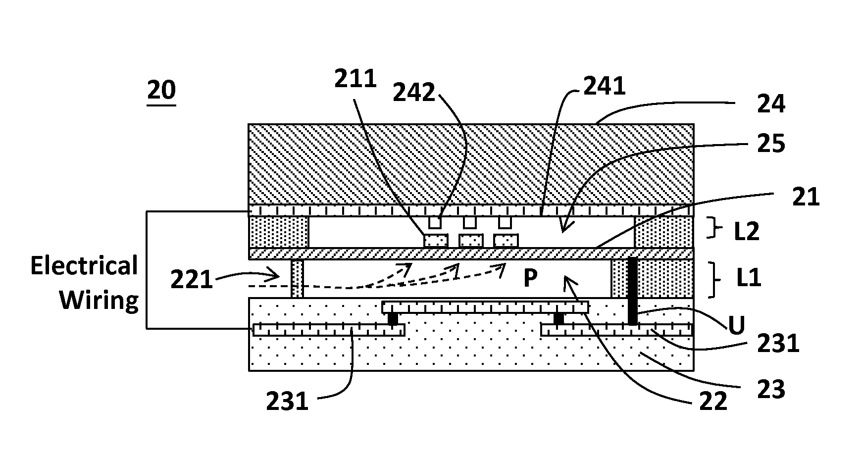
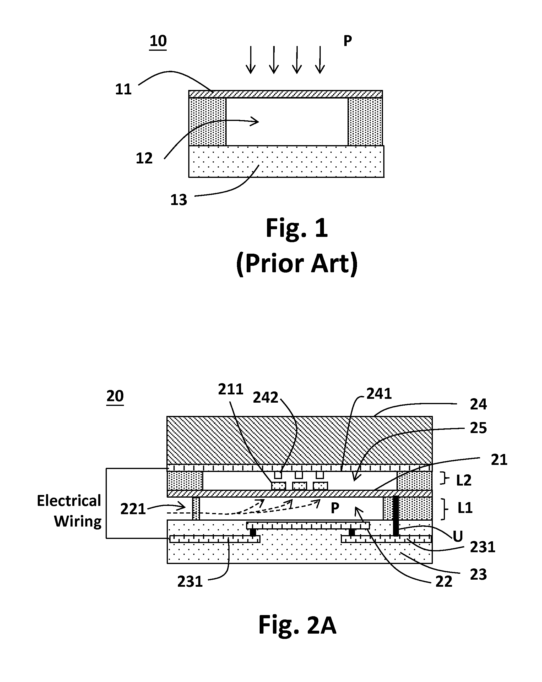
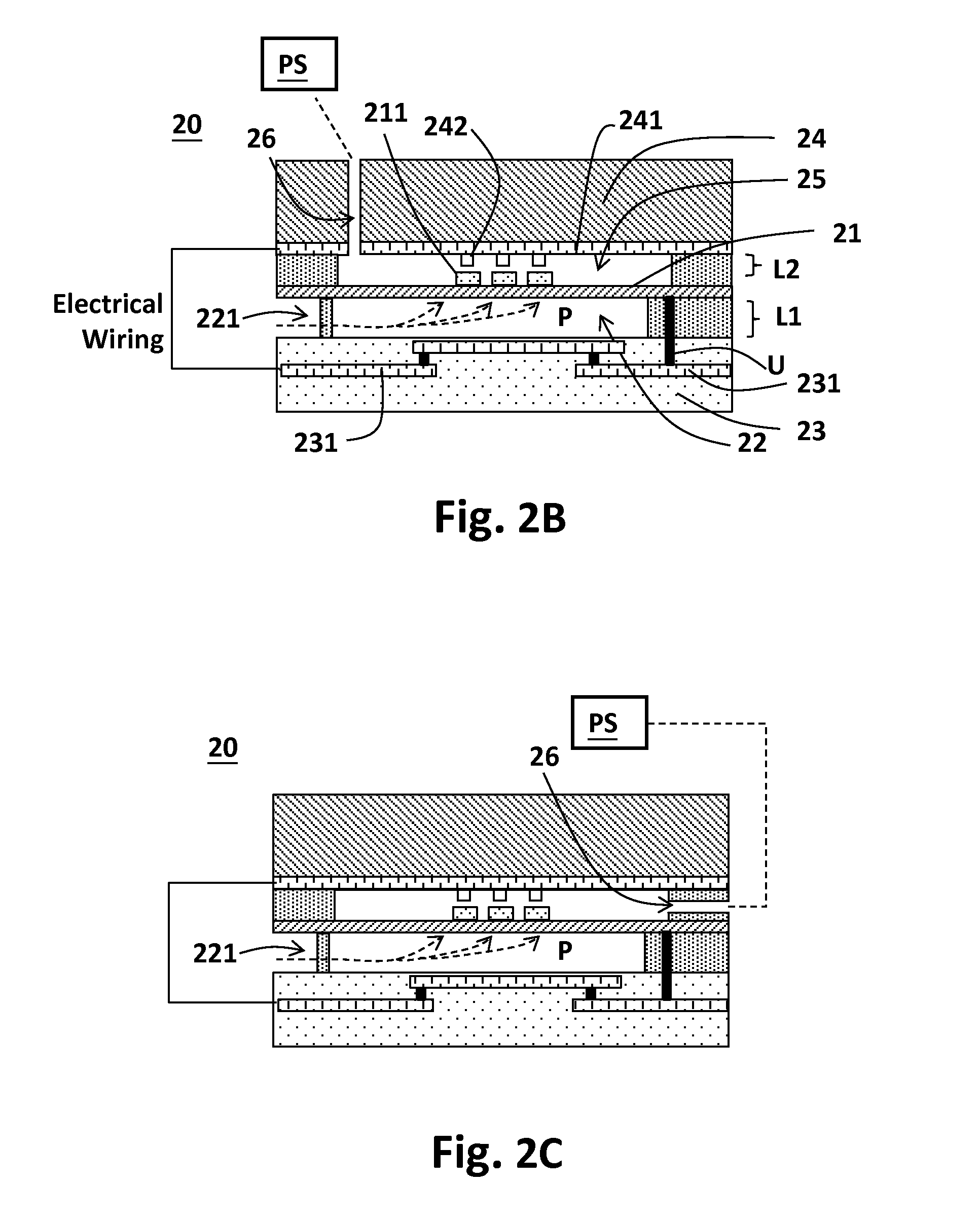
[0031]Referring to FIG. 2A, the present invention provides a MEMS pressure sensor 20 which comprises: a substrate 23 including at least one conductive wiring 231, wherein the substrate 23 includes for example but not limited to a bottom silicon substrate (or a bottom substrate made of another material) and a conductive wiring on or in the bottom silicon substrate, formed for example by steps of lithography, ion implantation, deposition, and / or etching, etc.; a semi-open chamber 22 above the conductive wiring 231, between the conductive wiring 231 and a membrane 21, the semi-open chamber 22 having an opening 221 to receive an...


PUM

PropertyMeasurementUnit
pressureaaaaaaaaaa
conductiveaaaaaaaaaa
thicknessaaaaaaaaaa

Abstract

The invention provides a micro-electro-mechanical system pressure sensor. The micro-electro-mechanical system pressure sensor includes: a substrate, including at least one conductive wiring; a membrane disposed above the substrate to form a semi-open chamber between the membrane and the substrate, the semi-open chamber having an opening to receive an external pressure; and a cap, disposed above the membrane and forming an enclosed space with the membrane, the cap including a top electrode corresponding to the membrane and at least one portion of the membrane forming a bottom electrode, wherein the top and bottom electrodes form a sensing capacitor to sense the external pressure.

Description

CROSS REFERENCE[0001]The present invention claims priority to TW 103109852, filed on Mar. 17, 2014, and TW 103119642, filed on Jun. 6, 2014.BACKGROUND OF THE INVENTION[0002]1. Field of Invention[0003]The present invention relates to a micro-electro-mechanical system pressure sensor, which includes a semi-open chamber to receive an external pressure and a membrane disposed over the semi-open chamber.[0004]2. Description of Related Art[0005]Micro-electro-mechanical system (MEMS) pressure sensors are commonly used nowadays, in applications such as altitude meters, microphones, pressure sensors in engine management systems, etc. FIG. 1 shows a prior art MEMS pressure sensor 10, which includes a membrane 11, an enclosed space 12, and a substrate 13. The membrane 11 deforms according to an external pressure P to generate a sensing signal. This prior art has an advantage of simple structure, but it has the following drawback. During manufacturing the MEMS device, the semiconductor manufact...

Claims


Application Information

Patent Timeline
Patent Type & Authority Applications(United States)
IPC IPC(8): G01L9/00B81B7/00B81C1/00
CPCG01L9/0005B81C1/00293B81B2201/0264B81C1/00158B81B7/0041B81C1/00309G01L9/0072G01L19/0618
Inventor HSU, YU-WENWU, CHIA-YULIN, SHIH-CHIEHLIN, SHIH-TING
Owner RICHTEK TECH
Learn More