
System and Method for Calculating Remaining Useful Time of Objects

a technology of useful time and system, applied in the field of system and method for predicting the remaining useful time of engineering assets, can solve the problems of loss of productivity, safety and environmental problems, and loss of more than $120 billion in the us industries

Active Publication Date: 2015-09-17
SPARKCOGNITION INC
View PDF1 Cites 81 Cited by
  • Summary
  • Abstract
  • Description
  • Claims
  • Application Information

AI Technical Summary

Benefits of technology

The present invention provides a system and method for predicting the remaining useful life of mechanical components, such as bearings, based on available condition monitoring data. The system automatically decides which columns of input information may be significant for predicting the remaining useful life of bearings and performs an analysis of both test bearings and training bearings to determine which training bearings are most similar to a given test bearing. The system can also build an automated model to predict the RUL of additional sensor-monitored mechanical assets and train an artificial neural network. Overall, the invention improves the accuracy and reliability of predicting the remaining useful life of mechanical components.

Problems solved by technology

Failures in industrial machinery can result in the loss of productivity and may lead to safety and environmental problems.
Bearing failure is one of the leading causes of such machinery malfunction.
More than $120 billion is lost across US industries due to the downtime and repair of bearings.
Equipment must be replaced before it fails, however it is difficult to predict when it is time for machinery to be replaced.
Thus, it is often the case that some equipment is replaced even though it could have operated safely for much longer, while other equipment may fail before being replaced.
A typical problem in RUL prediction is distinguishing noise from information.
Data files for bearings typically consist of hundreds of columns and it is challenging to decide which of these columns are significant for use in RUL prediction.

Method used


Image

  • System and Method for Calculating Remaining Useful Time of Objects
  • System and Method for Calculating Remaining Useful Time of Objects
  • System and Method for Calculating Remaining Useful Time of Objects

Examples


Embodiment Construction

[0012]The following description is provided to assist in a comprehensive understanding of exemplary embodiments of the invention as defined by the claims and their equivalents. It includes various specific details to assist in that understanding; however these specific details are to be regarded as merely exemplary. Accordingly, those of ordinary skill in the art will recognize that various changes and modifications of the embodiments described herein can be made without departing from the scope and spirit of the invention.

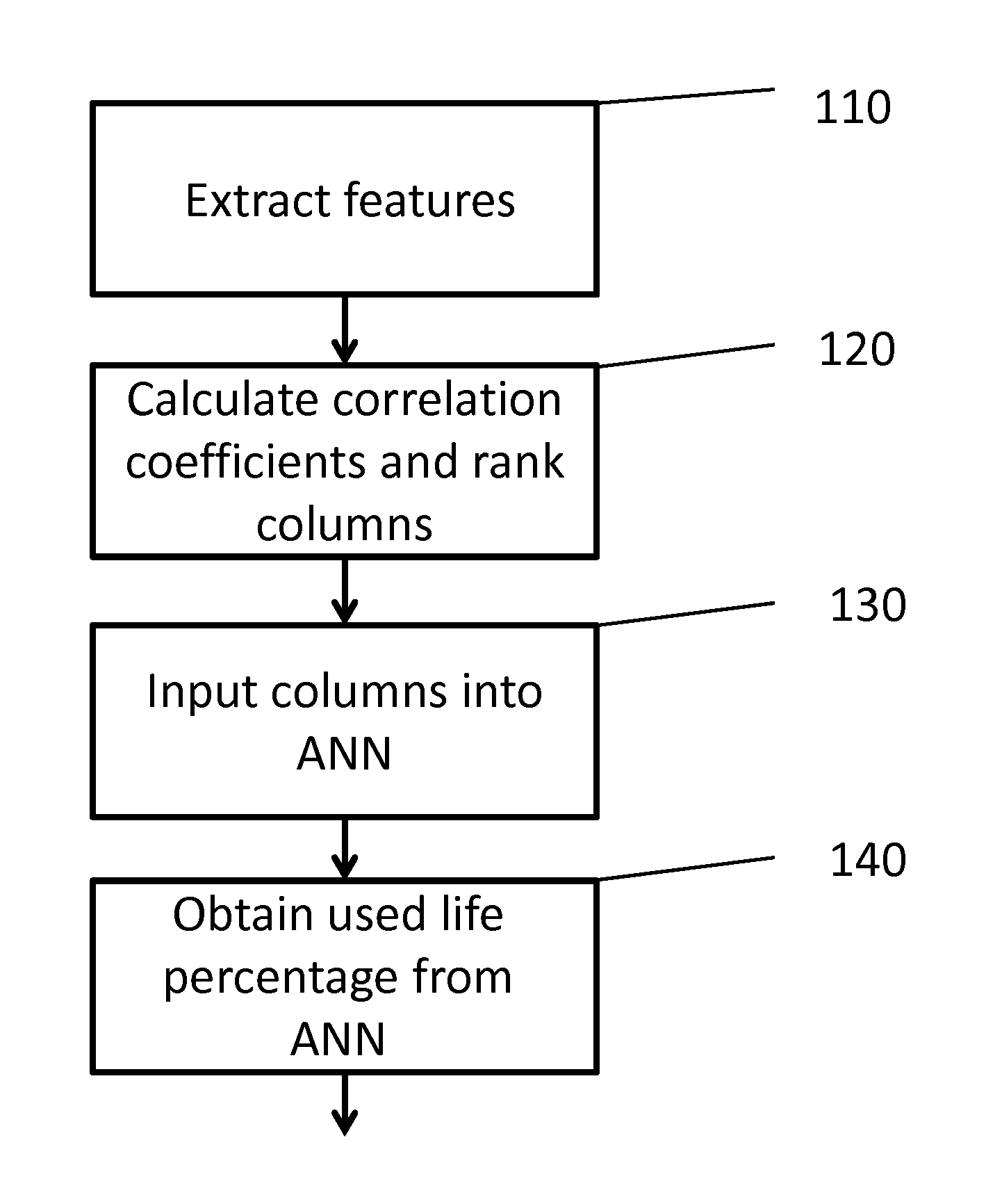
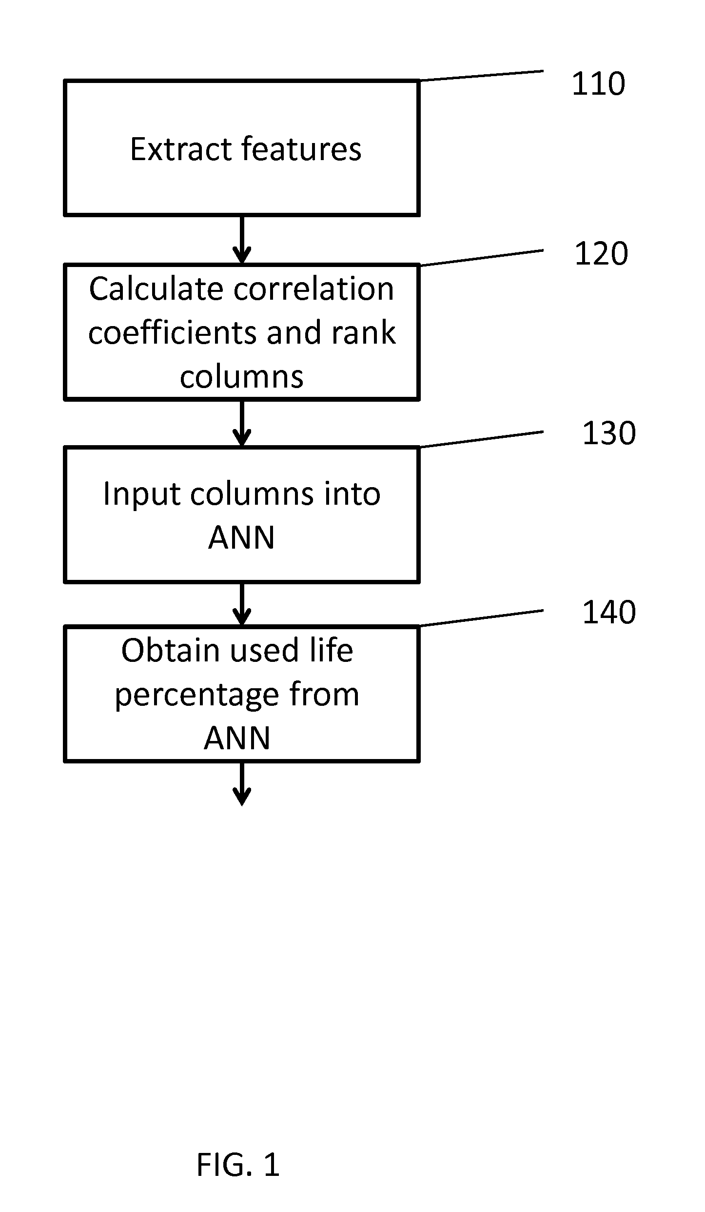
[0013]FIG. 1 is a high level block diagram of a process for obtaining a used life percentage according to an exemplary embodiment of the present invention. Referring now to FIG. 1. In step 110, features are extracted from vibration signals of mechanical components such as a set of bearings in both time and frequency domains. In one embodiment, time domain features include root mean square (rms), peak, crest factor, and kurtosis of the vibration signal, while frequ...


PUM


Abstract

An aspect of the present invention is to provide a system and method for predicting the remaining useful time of mechanical components such as bearings. Another aspect of the present invention is to provide a system and method for predicting the remaining useful time of bearings based on available condition monitoring data. Another aspect of the present invention is to provide a system and method for automatically deciding which columns of input information are the most significant for predicting the remaining useful life of bearings. Another aspect of the present invention is to provide a system and method for performing an analysis of both test bearings and training bearings and determining which training bearings are most similar to a given test bearing. Another aspect of the present invention is to provide a system and method for training an artificial neural network.

Description

RELATED APPLICATIONS[0001]This application claims the benefit of and priority to U.S. provisional application No. 61 / 951,176, filed Mar. 11, 2014, which is hereby incorporated herein by reference in its entirety.FIELD OF THE INVENTION[0002]The present invention relates to a system and method for predicting remaining useful time of objects. More particularly, the present invention relates to a system and method for predicting the remaining useful time of engineering assets, such as bearings based on available condition monitoring data.DESCRIPTION OF RELATED ART[0003]Failures in industrial machinery can result in the loss of productivity and may lead to safety and environmental problems. Bearing failure is one of the leading causes of such machinery malfunction. More than $120 billion is lost across US industries due to the downtime and repair of bearings. Equipment must be replaced before it fails, however it is difficult to predict when it is time for machinery to be replaced. Thus,...

Claims


Application Information

Patent Timeline
Patent Type & Authority Applications(United States)
IPC IPC(8): G06N3/08G06N7/00
CPCG06N7/005G06N3/08G01M13/04
Inventor HUSAIN, SYED MOHAMMAD AMIRABEL, MARTIN ANDREASIQBAL, QASIM
Owner SPARKCOGNITION INC
Learn More