Terminal device cover and a terminal device for contactless charging

a terminal device and charging terminal technology, applied in electric vehicles, transportation and packaging, electric power, etc., can solve the problems of reducing the efficiency of contactless energy transfer etc., and achieve the effect of reducing the efficiency of contactless energy transfer and reducing the sensitivity of wireless communications antennas

Inactive Publication Date: 2015-09-24
SONY MOBILE COMM INC
View PDF8 Cites 16 Cited by
  • Summary
  • Abstract
  • Description
  • Claims
  • Application Information

AI Technical Summary

Benefits of technology

[0007]In a conventional terminal device, the power receiving coil for contactless power transfer is collocated with device's communications antenna on the back side of the device. For example, the antenna and circuitry for near field communication (NFC), cellular communication, Wi-Fi, Bluetooth™, etc. are in many cases arranged on the back side of the terminal device. The close proximity of the power reception coil and the communication antenna is mutually detrimental to both the power reception coil and the communication antenna. The presence of the coil decreases the sensitivity of the wireless communications antenna, and the presence of the wireless communications antenna decreases the efficiency of the contactless energy transfer.

Problems solved by technology

The close proximity of the power reception coil and the communication antenna is mutually detrimental to both the power reception coil and the communication antenna.
The presence of the coil decreases the sensitivity of the wireless communications antenna, and the presence of the wireless communications antenna decreases the efficiency of the contactless energy transfer.

Method used


Image

  • Terminal device cover and a terminal device for contactless charging
  • Terminal device cover and a terminal device for contactless charging
  • Terminal device cover and a terminal device for contactless charging

Examples


Embodiment Construction

[0026]Referring now to the drawings, wherein like reference numerals designate identical or corresponding parts throughout the several views.

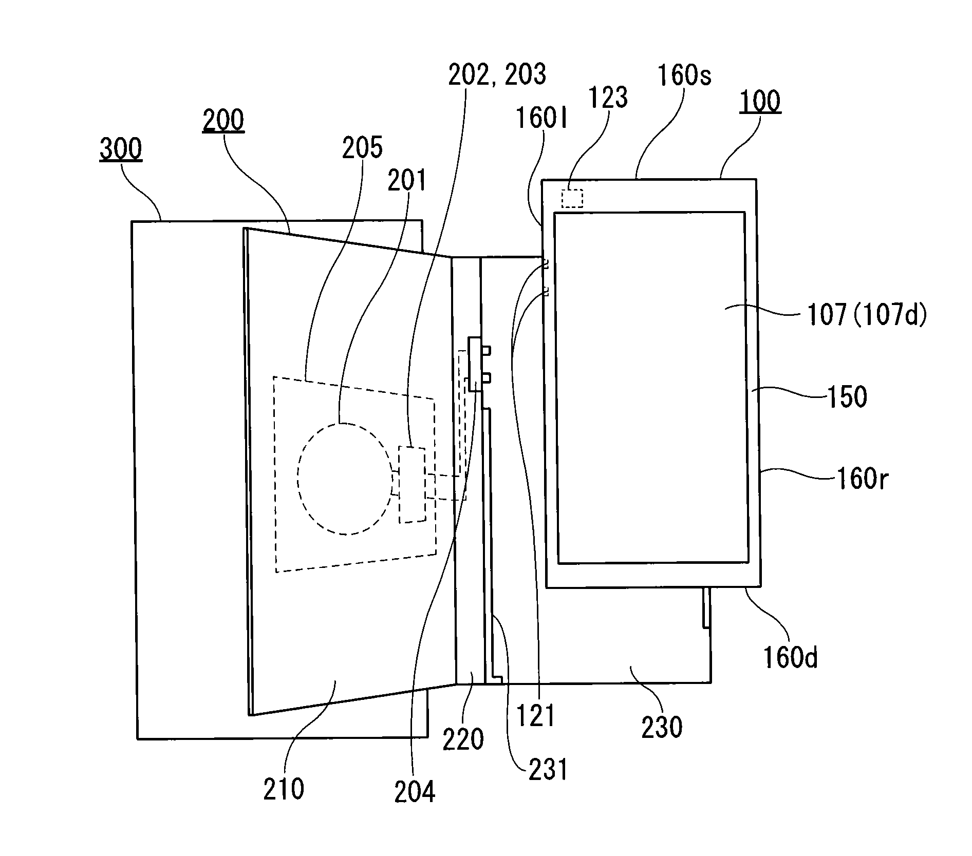
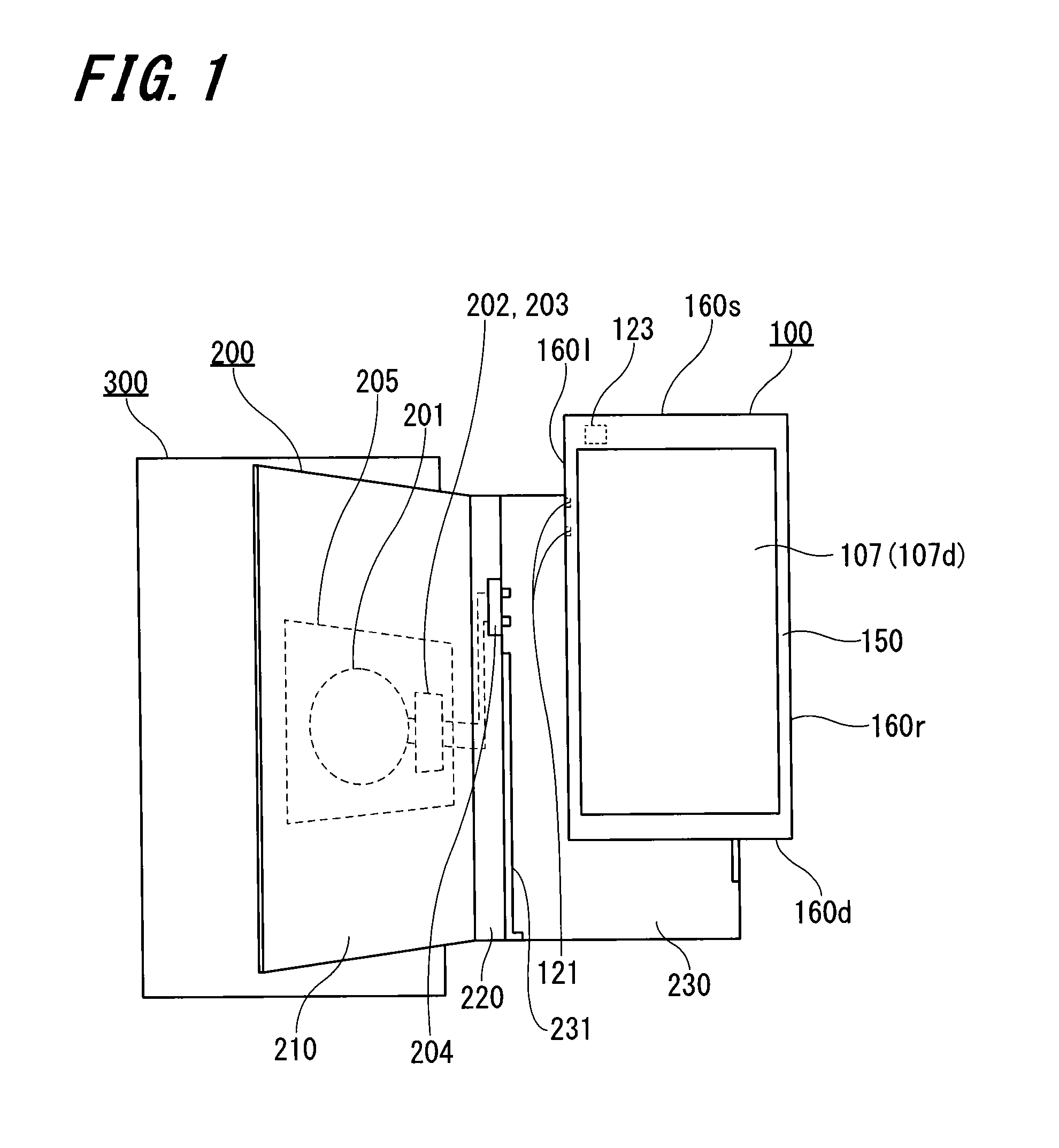
[0027]Referring first to FIG. 1, FIG. 1 illustrates a non-limiting example of a terminal device 100 arranged with a terminal device cover 200 and a charging device 300. FIG. 1 is a front view which shows the external structural appearance of the terminal device 100 arranged with respect to the terminal device cover 200 and the charging device 300. The charging device 300 performs contactless energy transfer with respect to the cover 200. The charging device can be formed in a pad shape, and a coil for power transmission may be incorporated in the inside of the charging device 300.

[0028]The touch panel 107 is provided in the front face portion of the terminal device 100. The touch panel 107 includes a touch sensor and a display 107d which may be either laminated or integrally formed in the touch panel 107. The display 107d displays a character, ...


PUM


Abstract

A terminal device cover having a front surface part, a lateral surface part, and a rear surface part. The terminal device cover is arranged so as to accommodate a terminal device. The front surface part, lateral surface part, and rear surface part of the cover are respectively arranged to cover a front surface, lateral surface, and rear surface of a terminal device. Circuitry configured to receive wireless electrical energy transmission is arranged in the front surface part of the terminal device cover. This circuitry includes a power receiving circuit, a rectifier circuit, and a charging output terminal. The power receiving section is adapted to receive electrical power transmitted from a non-contact power transmission device. The rectifier circuit rectifies the received power, and the charging output terminal is connects to a terminal device charging terminal in order to transfer electrical power to the terminal device.

Description

BACKGROUND[0001]1. Technical Field[0002]The present disclosure relates to a cover for contactless charging of a terminal device such as a mobile phone, smart phone, a tablet device, or the like.[0003]2. Description of the Related Art[0004]In recent years, the technology for contactless electrical energy transfer has attracted attention in the area of terminal devices, such as smart phones and tablet devices. This technology is sometimes referred to as wireless power, wireless energy transmission, contactless energy transfer, wireless charging, etc. Exemplary methods of contactless power transfer include: electromagnetic induction, resonant magnetic induction, etc.[0005]In an electromagnetic induction type apparatus for contactless power transfer, both the power transmission side of the apparatus and the power receiver side of the apparatus have coils. Through the mutual inductive coupling between these two coils, changes in the current of the power transmission coil induces a voltag...

Claims


Application Information

Patent Timeline
Patent Type & Authority Applications(United States)
IPC IPC(8): H02J7/02H02J7/00
CPCH02J7/0042H02J7/025H02J50/10H02J7/0044H02J50/20H02J50/70H02J50/12
Inventor SHIRAKAWA, HIROSHI
Owner SONY MOBILE COMM INC
Why Eureka
Try Eureka