
Method of operating crude treatment system

a crude treatment and crude technology, applied in the field of crude treatment technology, can solve the problems of increasing crude demand, increasing crude demand, increasing cost, etc., and achieve the effect of suppressing an increase in the content of the catalytic poison

Inactive Publication Date: 2015-10-01
JGC CORP
View PDF3 Cites 7 Cited by
  • Summary
  • Abstract
  • Description
  • Claims
  • Application Information

AI Technical Summary

Benefits of technology

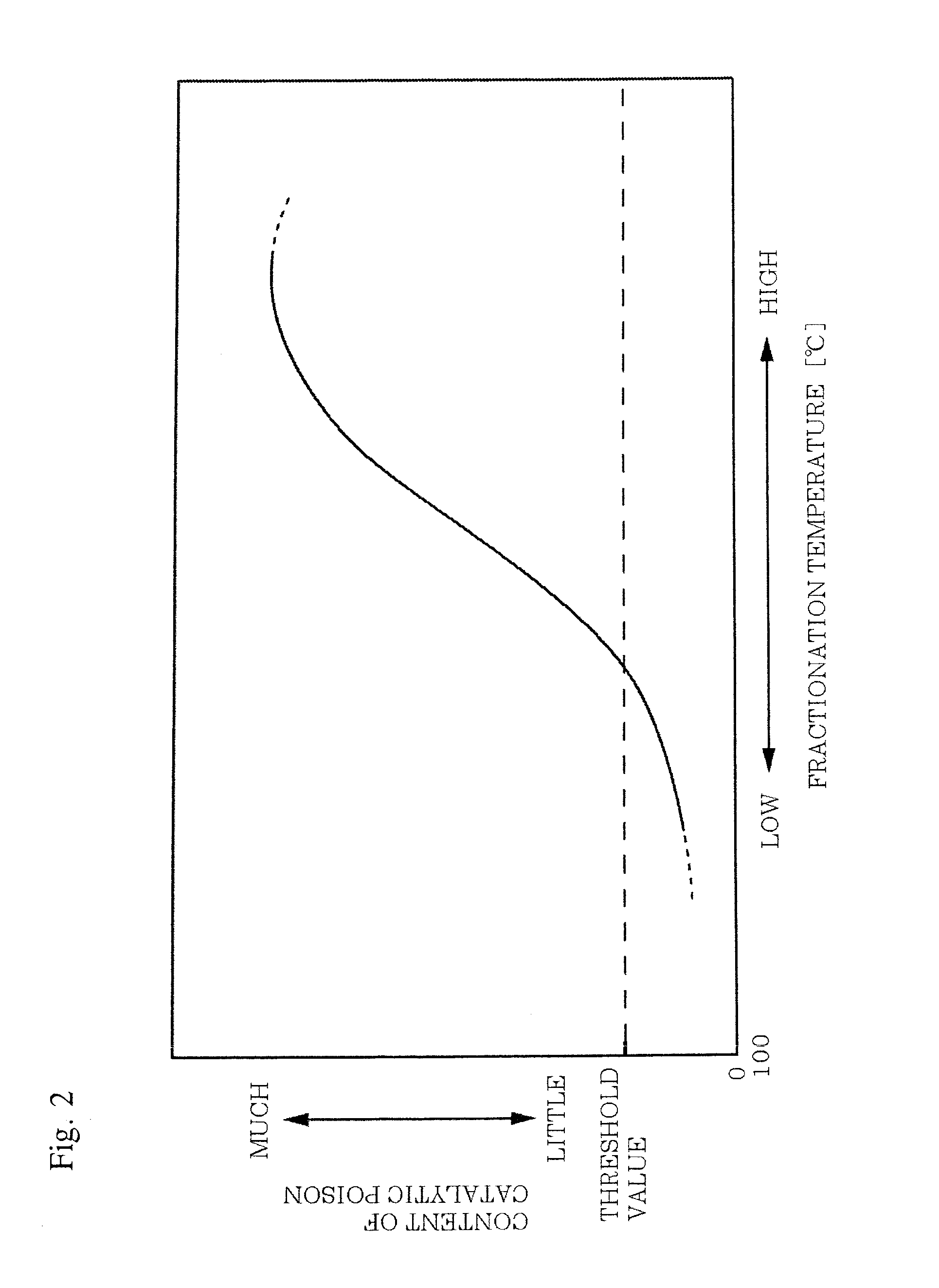
The first invention introduces a secondary distillation tower that can handle crude with a high level of catalytic poison. This allows for the extraction of a light fraction from the crude while minimizing the poison content in the residue fraction. This results in a heavy product that can be created without impacting the downstream catalytic cracking process. The second invention expands on this idea by allowing the extraction of a light fraction with a low level of cataltic poison from the crude. This means that a wider range of crudes can be used in the treatment system without affecting the overall process.

Problems solved by technology

In recent years, a demand for a heavy crude treatment increases due to an increase in demand for crude, an increase in cost, and a limitation in production, Meanwhile, properties of heavy crude have a large influence on a downstream unit for treating various fractions fractionated from a crude distillation unit (CDU) as a primary unit.
However, since the RDSU is one of the expensive units of the petroleum refinery, from the economic viewpoint, it is difficult to construct the RDSU for producing a heavy product from crude.
However, in the technology disclosed in PTL 1, a condition of a high temperature and a high pressure is required because the subcritical water or supercritical water is used, and a cost involved with the unit or operation increases because the oxidizer or capture agent is consumed.
Meanwhile, there is no description for a technology of removing nickel or CCR from the atmospheric residue, and there still remains a problem in that the activity of the catalyst used in the catalytic cracking process is degraded,

Method used


Image

  • Method of operating crude treatment system
  • Method of operating crude treatment system
  • Method of operating crude treatment system

Examples


Embodiment Construction

[0021]Hereinafter, a crude treatment system will be described which treats crude containing a comparatively large content of catalytic poisons such as CCR, V, and Ni and supplies raw materials to, for example, RFCCU.

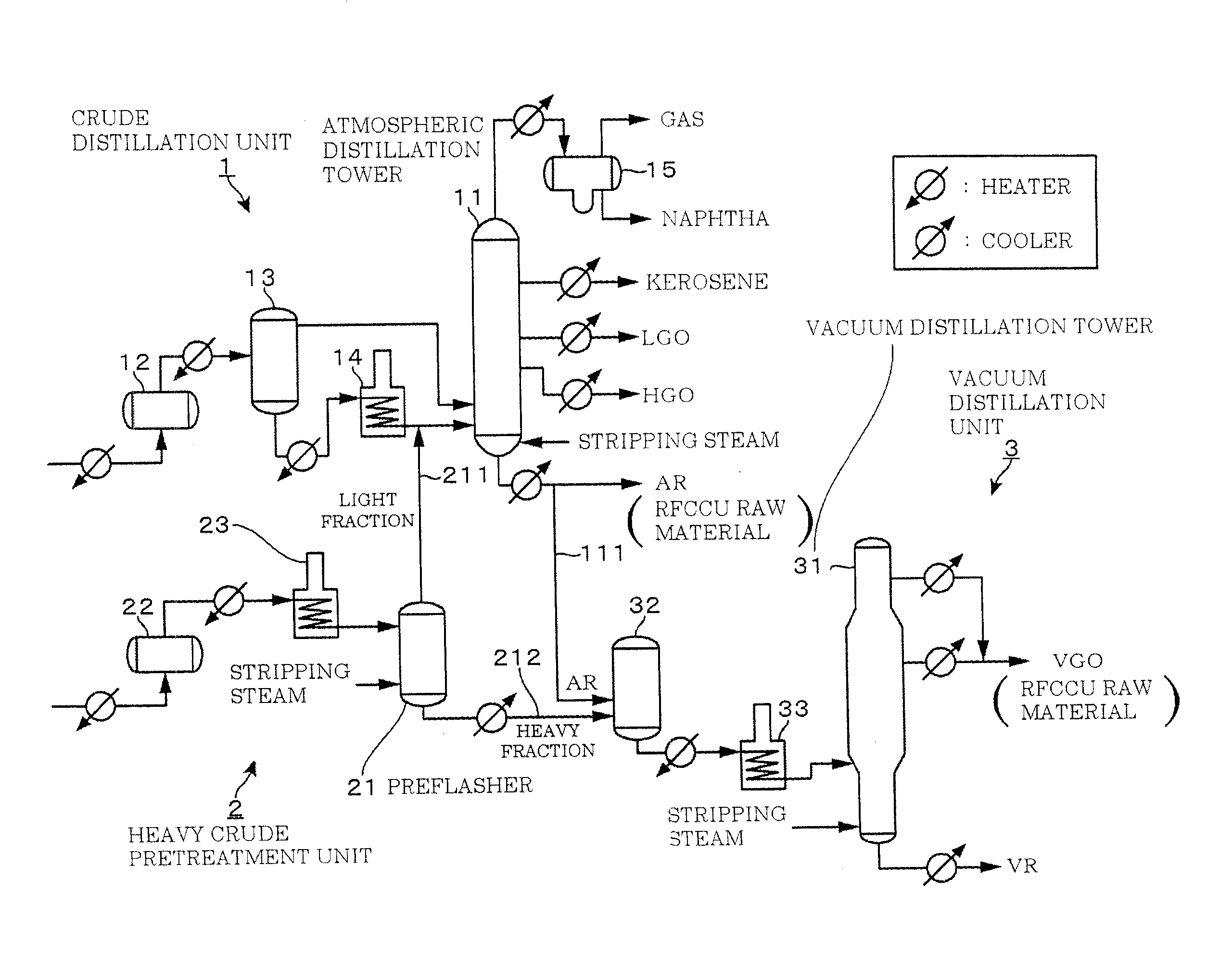
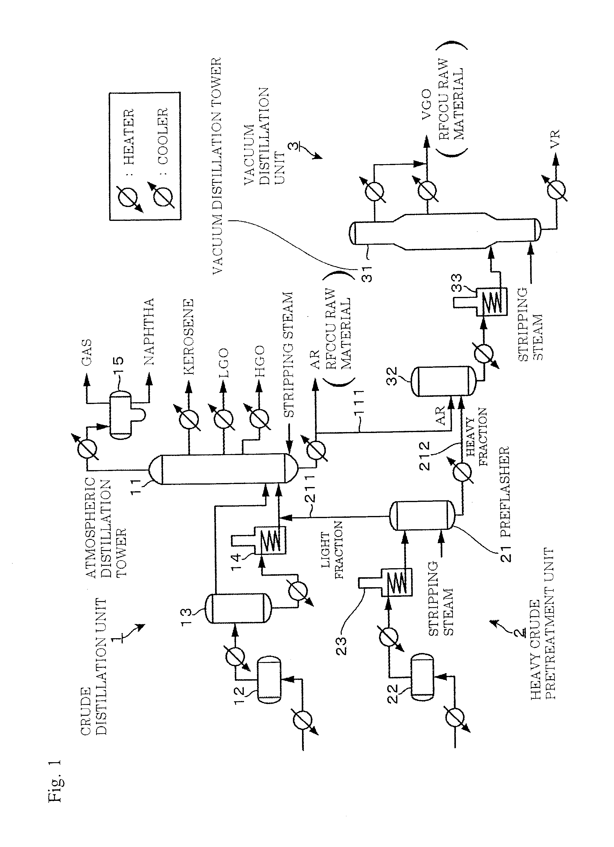
[0022]FIG. 1 is an explanatory diagram showing a configuration of a crude treatment system according to the embodiment. The crude treatment system includes, for example, a crude distillation unit 1 which distills light crude containing a small content of CCR, V, and Ni in an atmospheric pressure state, a vacuum distillation unit 3 which distills AR fractionated from the crude distillation unit 1 in a vacuum condition, and a heavy crude pretreatment unit 2 which pretreats heavy crude having a comparatively large content of CCR, V, and Ni so as to send a fraction, not causing a degradation of a catalyst in a downstream catalytic cracking process even when the fraction is treated in the crude distillation unit 1, to the crude distillation unit 1 and to send a fraction havin...


PUM

PropertyMeasurementUnit
temperatureaaaaaaaaaa

Abstract

Crude containing a comparatively large content of nickel, vanadium, or carbon residue is treated so as to supply a raw material to a downstream catalytic cracking process, A primary distillation tower fractionates first crude into a residue fraction partly used as raw oil of a catalytic cracking process and other fractions. A secondary distillation tower fractionates second crude containing a larger content of a catalytic poison with respect to catalysts used in the catalytic cracking process than the first crude into a light fraction included in a distillation temperature range of the other fractions and a heavy fraction as a rest thereof. A light fraction supply line supplies the light fraction to the primary distillation tower so as to be treated in the primary distillation tower.

Description

TECHNICAL FIELD[0001]The present invention relates to a technology of treating crude containing a catalytic poison with respect to a catalyst of a catalytic cracking process.BACKGROUND ART[0002]In recent years, a demand for a heavy crude treatment increases due to an increase in demand for crude, an increase in cost, and a limitation in production, Meanwhile, properties of heavy crude have a large influence on a downstream unit for treating various fractions fractionated from a crude distillation unit (CDU) as a primary unit.[0003]For example, a carbon residue (hereinafter, a carbon residue specified in Conradson (JIS K2270-1) is referred to as a CCR (Conradson Carbon Residue)), vanadium (V) , or nickel (Ni) abundantly contained in heavy crude causes an increase in the yield of cokes or offgas or a degradation of catalytic activity in a catalytic cracking process using a residue fluid catalytic cracking unit (hereinafter, referred to as a RFCCU) for cracking atmospheric residue (her...

Claims


Application Information

Patent Timeline
Patent Type & Authority Applications(United States)
IPC IPC(8): C10G7/08
CPCC10G7/08C10G11/18
Inventor SAWAI, NAOAKIMIZUGUCHI, YOSHIHIRO
Owner JGC CORP
Learn More