Cavitation-based hydro-fracturing technique for geothermal reservoir stimulation

a geothermal reservoir and cavitation-based technology, applied in the direction of machines/engines, mechanical equipment, borehole/well accessories, etc., can solve the problems of reducing heat exchange efficiency, bypassing the targeted fracture network or even fault movement, and lack of effective control, so as to increase permeability and enhance heat transfer

Active Publication Date: 2015-10-01
UT BATTELLE LLC
View PDF2 Cites 11 Cited by
  • Summary
  • Abstract
  • Description
  • Claims
  • Application Information

AI Technical Summary

Benefits of technology

[0014]According to another example, a method includes: lowering an apparatus as described above into a well casing; pressurizing the pressure chamber with the working fluid using a pump connected to the inlet aperture via a conduit; rotating the shutter with the powering device; discharging the working fluid from the pulse cavity; generating a pressure fluctuation near the liquid and rock interface with the working fluid to induce cavitation on the rock surface; and fracturing the rock to create a network of micro-fissures for increased permeability and enhanced heat transfer.

Problems solved by technology

A potential drawback of using hydrofracking techniques is the lack of effective control in the creation of large fractures, which could result in by-pass of targeted fracture network or even fault movement in the rock formation.
The loss of hydraulic medium can reduce heat exchange efficiency and increase the cost of the development of EGS.
The use of chemicals along with the unpredictable fault movement may also adversely impact the environment.
Ultimately, the dynamic stress can contribute to the fatigue of the target surface, including micro-cracks that form and coalesce on the surface 204, eventually leading to material removal known as cavitation damage.

Method used


Image

  • Cavitation-based hydro-fracturing technique for geothermal reservoir stimulation
  • Cavitation-based hydro-fracturing technique for geothermal reservoir stimulation
  • Cavitation-based hydro-fracturing technique for geothermal reservoir stimulation

Examples


Embodiment Construction

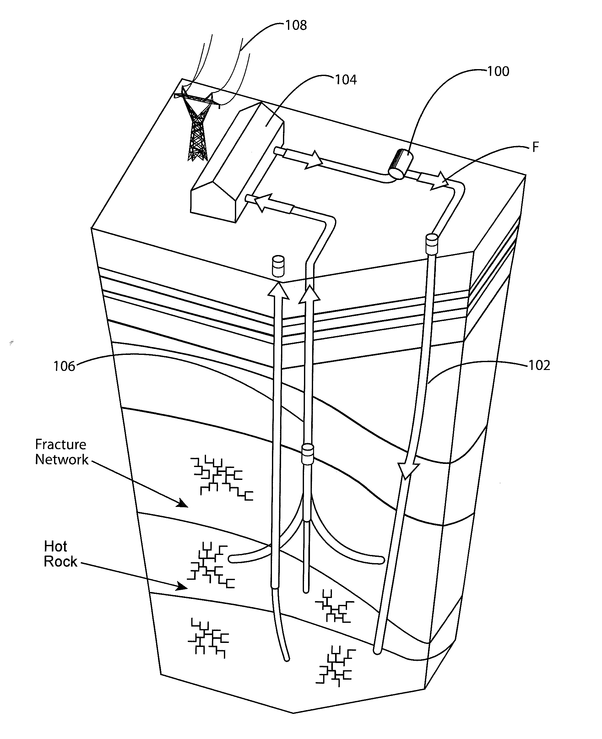
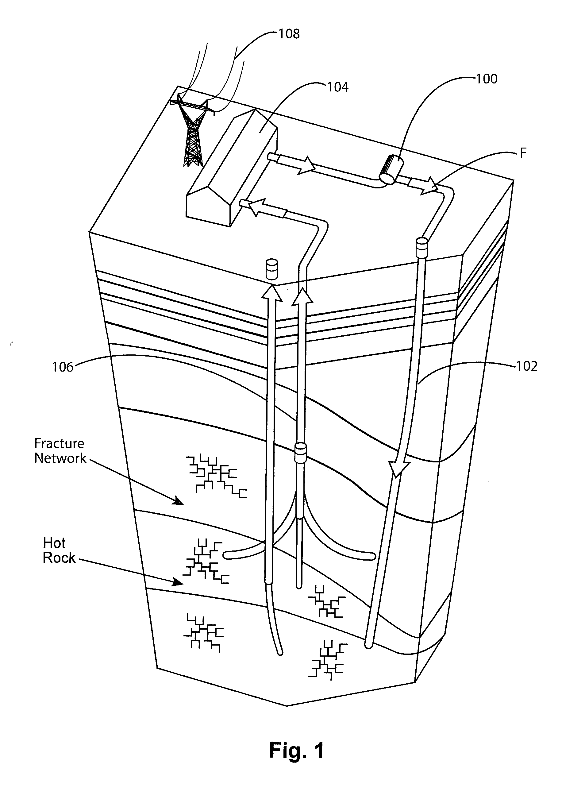
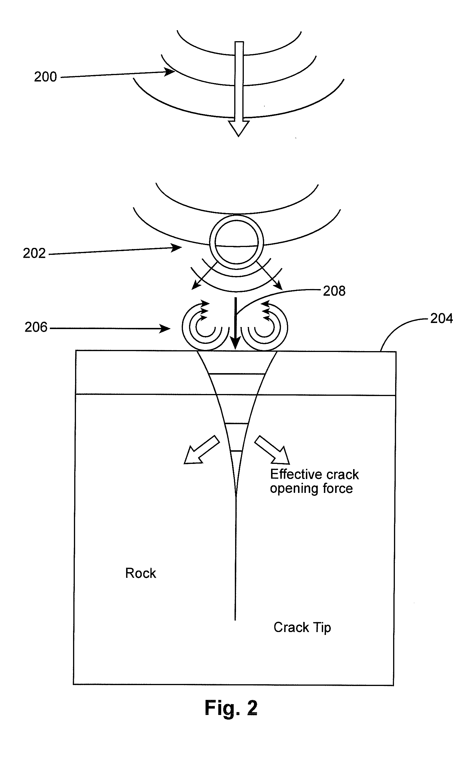
[0023]Cavitation can be created by generating pressure fluctuation at the liquid / solid interface. In addition to the liquid phase changes in EGS, bubbles will form when the liquid pressure in the flow fluctuates below the cavitation threshold pressure. Cavitation induced localized shock waves and micro jets can effectively generate surface pitting. The repetitive cavitation events due to collapse of large cluster of bubbles can further induce more intense shock waves to fatigue the hot rock surfaces and develop extensive surface crack networks, in addition to the progressively increased crack depth. Cavitating intensity can be controlled by changing the magnitude of the pressure variation as well as the frequency. Such a fracturing process is much less intrusive than the conventional techniques to the integrity of the rock formation, thus it will extend the lifetime of EGS reservoirs and reduce the potential of fault movement induced earth instability. Furthermore, it has the benefi...


PUM


Abstract

A rotary shutter valve 500 is used for geothermal reservoir stimulation. The valve 500 includes a pressure chamber 520 for holding a working fluid (F) under pressure. A rotatable shutter 532 is turned with a powering device 544 to periodically align one or more windows 534 with one or more apertures 526 in a bulkhead 524. When aligned, the pressurized working fluid (F) flows through the bulkhead 524 and enters a pulse cavity 522, where it is discharged from the pulse cavity 522 as pressure waves 200. The pressure wave propagation 200 and eventual collapse of the bubbles 202 can be transmitted to a target rock surface 204 either in the form of a shock wave 206, or by micro jets 208, depending on the bubble-surface distance. Once cavitation at the rock face begins, fractures are initiated in the rock to create a network of micro-fissures for enhanced heat transfer.

Description

CROSS-REFERENCE TO RELATED APPLICATIONS[0001]This patent application is related to United States application Ser. No. ______ filed on DD-MM-YYYY and entitled, A CAVITATION-BASED HYDRO-FRACTURING SIMULATOR, the entire contents of which are included herein by reference as if included at length.STATEMENT REGARDING FEDERALLY SPONSORED RESEARCH AND DEVELOPMENT[0002]This invention was made with government support under Contract No. DE-AC05-000822725 awarded by the U.S. Department of Energy. The government has certain rights in the invention.THE NAMES OF THE PARTIES TO A JOINT RESEARCH AGREEMENT[0003]None.BACKGROUND OF THE INVENTION[0004]1. Field of the Invention[0005]The present disclosure relates to geothermal energy production and particularly to apparatuses and methods for supporting Enhanced Geothermal Systems (EGS).[0006]2. Description of the Related Art[0007]Geothermal energy is an important part of the nation's renewable energy initiative. FIG. 1 illustrates a simplified schematic ...

Claims


Application Information

Patent Timeline
Patent Type & Authority Applications(United States)
IPC IPC(8): E21B43/26
CPCE21B43/26E21B28/00F03G7/04F24T10/20F24T2010/53Y02E10/10
Inventor WANG, JY-AN JOHNWANG, HONGREN, FEICOX, THOMAS S.
Owner UT BATTELLE LLC
Why Eureka
Try Eureka