Oil-free turbocharger bearing assembly having conical shaft supported on compliant gas bearings

a technology of gas bearings and conical shafts, which is applied in the direction of sliding contact bearings, engine components, mechanical equipment, etc., can solve the problems of foil bearing supported turbomachinery failure, large gas film thickness, and further heat the bearing area, so as to improve thermal management, improve the damping of the bearing, and remove excess heat easily

Active Publication Date: 2015-10-01
BORGWARNER INC
View PDF22 Cites 19 Cited by
  • Summary
  • Abstract
  • Description
  • Claims
  • Application Information

AI Technical Summary

Benefits of technology

[0016]Two conical rotor elements are placed end to end on the shaft to be supported. The conical rotor elements have the shape of a truncated right circular cone and thus have a large end corresponding to the base of the cone, and a small end corresponding to the frustrum of the truncated cone. The conical elements face in opposite directions and thus, the large ends of the cones may be placed together, or the small ends of the cone may be placed together. The conical rotor elements are supported on gas foil bearings. Because of the conical shape of the rotor elements, the bearing supporting each element, provides both radial and axial support, and thus the bearing assembly fills the role of both the journal bearing and the thrust bearing. Conical bearings also allow the removal of excessive heat easily from the air film thereby controlling the thermal expansion of the components. This feature enables better thermal management to prevent bearing seizure and thermal instability.

Problems solved by technology

The rapid rotation of the turbine shaft creates frictional forces which further heat the bearing area.
In practice, foil bearing supported turbomachinery fails, at extreme operating conditions (high temperature and high rotating shaft speeds), due to poor thermal management.
In particular, thermoelastic distortion of the thrust runner due to heat transfer within the bearing system results in deformations larger than the gas film thickness, which causes system failure.
Thrust foil gas bearings have lower load capacity at extreme operation conditions because of difficulty in thermal management.

Method used


Image

  • Oil-free turbocharger bearing assembly having conical shaft supported on compliant gas bearings
  • Oil-free turbocharger bearing assembly having conical shaft supported on compliant gas bearings
  • Oil-free turbocharger bearing assembly having conical shaft supported on compliant gas bearings

Examples


Embodiment Construction

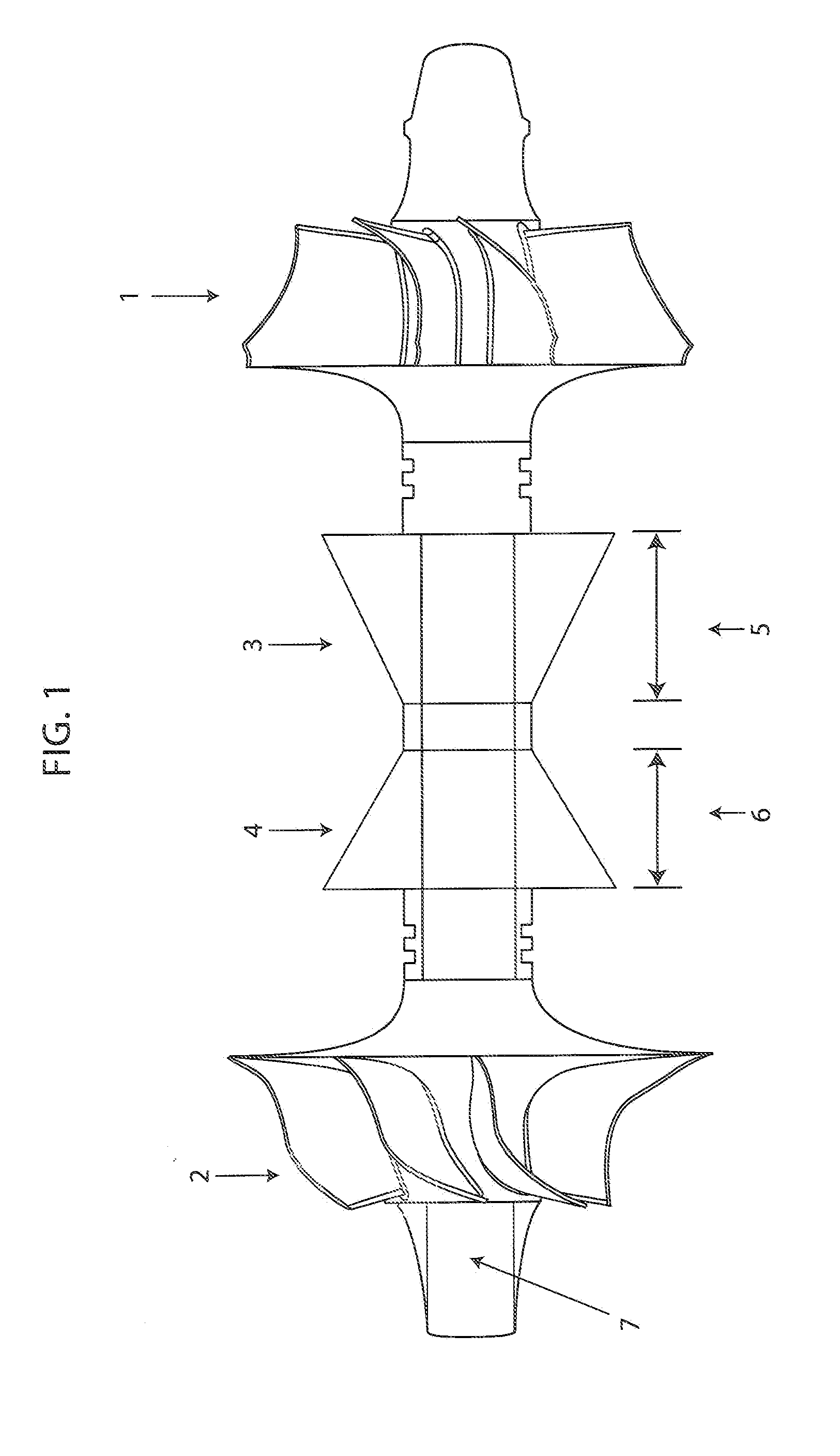
[0028]FIG. 1 illustrates a turbocharger shaft with conical rotor elements having the shape of a truncated right circular cone in which the small ends of the cone are mounted together. A turbine wheel (1), a compressor wheel (2), a first conical rotor element (3), having a length (5), and a second conical rotor element (4) having a length (6) are mounted on the turbocharger shaft (7).

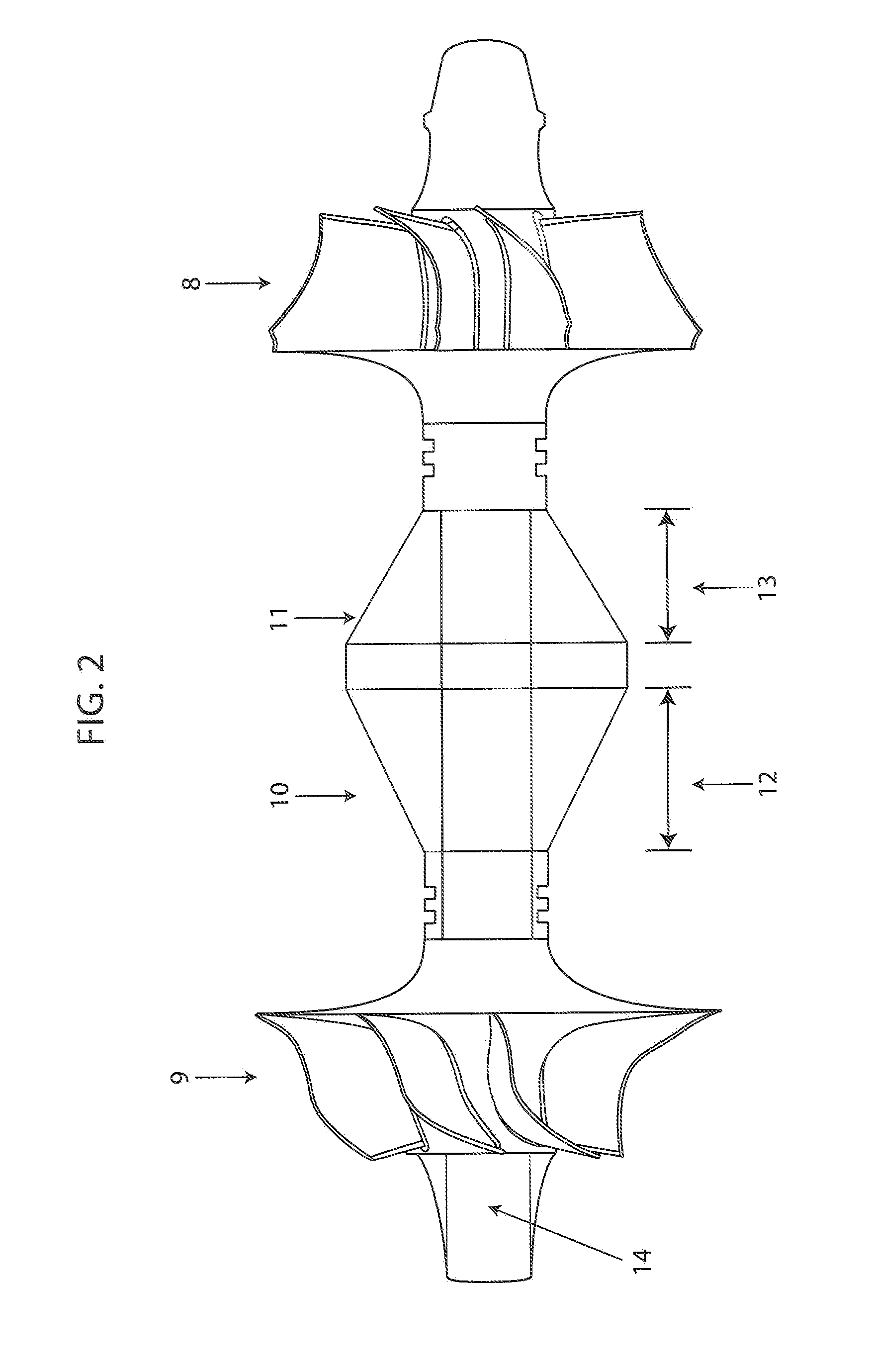
[0029]FIG. 2 illustrates a turbocharger shaft with conical rotor elements in which the large ends of the cone are mounted together. A turbine wheel (8), a compressor wheel (9), a first conical rotor element (10), having a length (12), and a second conical rotor element (11) having a length (13) are mounted on the turbocharger shaft (14).

[0030]FIG. 3 illustrates the components which make up the conical rotor assembly. The turbocharger shaft (18) has a turbine wheel (15) mounted at one end. The first conical rotor element (16) and the second conical rotor element (17) may be pressed onto the shaft (18). Wh...


PUM


Abstract

This invention provides a turbocharger bearing assembly having foil bearing assemblies (21, 22, 23, 24, 30, 35, 36, 37, 40, 41, 42, 45, 46, 47, 50, 52) supporting conical rotor elements (3, 4, 10, 11, 16, 17, 31, 32).

Description

CROSS-REFERENCE TO RELATED APPLICATION[0001]This application claims priority to and all the benefits of U.S. Provisional Application No. 61 / 714,909, filed on October 17, and entitled “An Oil-Free Turbocharger Bearing Assembly Having Conical Shaft Supported On Compliant Gas Bearings.”BACKGROUND OF THE INVENTION[0002]1. Field of the Invention[0003]This invention relates to a hydrodynamic gas foil bearing assembly having conical rotor elements. The bearing assembly is useful in turbochargers for internal combustion engines. The bearing assembly may also be used in other turbine applications such as small aircraft engines.[0004]2. Description of Related Art[0005]A turbocharger is a type of forced induction system used with internal combustion engines. Turbochargers deliver compressed air to an engine intake, allowing more fuel to be combusted, thus boosting an engine's horsepower without significantly increasing engine weight. Thus, turbochargers permit the use of smaller engines that d...

Claims


Application Information

Patent Timeline
Patent Type & Authority Applications(United States)
IPC IPC(8): F16C32/06F16C33/04
CPCF16C32/0603F16C33/04F16C32/0685F16C17/10F16C2360/24F16C17/024F16C27/02
Inventor RYU, KEUN
Owner BORGWARNER INC
Why Eureka
Try Eureka