Light distribution lens

a light distribution and lens technology, applied in the field of lenses, can solve the problem of not being able to obtain a complex light distribution as required, and achieve the effect of widen and smoothing the light distribution

Active Publication Date: 2015-10-01
NICHIA CORP +1
View PDF2 Cites 45 Cited by
  • Summary
  • Abstract
  • Description
  • Claims
  • Application Information

AI Technical Summary

Benefits of technology

[0043]In the present invention, since the lens has a double-peak shape in the long axis cross-sectional outline of the light emitting side, the light distribution spreads in the long-axis direction of the lens, and a wider light distribution is obtained in the long-axis direction in term of the distribution of luminous intensity.
[0044]In the short-axis cross-sectional outline of the light emitting side of the lens, owing to the existence of a straight-line part at and near the lens central optical axis, the light distribution at and around the short axis spreads out to the lateral sides in the long-axis and short-axis directions distant from the short axis, so that smoothly-diffused light distribution is obtained.
[0045]In addition, desired light distribution can be obtained by modifying the straight-line part provided near the lens central optical axis in cross sections parallel to the short-axis cross section.
[0046]In another embodiment of the present invention, in the vicinity of the lens central optical axis position, the lens has a straight-line part parallel to the short axis, which is also perpendicular to the lens long-axis cross section, in the outline of the light emitting side of not only the lens short-axis cross section but also lens cross sections that are taken along the planes parallel to the lens short-axis cross section. In particular, in the vicinity of the lens central optical axis position including said axis, the lens has a straight-line part parallel to the short axis, which is also perpendicular to the lens long-axis cross section, in the outline of the light emitting side of a lens cross section taken along a plane parallel to the lens short-axis cross section; therefore, the straight-line parts parallel to the short axis are continuously provided, so tha

Problems solved by technology

In addition, it was also impossible to obtain a complex light distribution as required, while maintaining an

Method used


Image

  • Light distribution lens
  • Light distribution lens
  • Light distribution lens

Examples


first embodiment

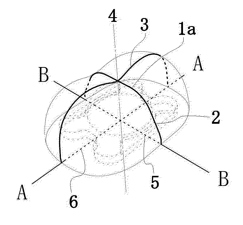
[0066]The light distribution lens according to the first embodiment of the present invention has a light-incident side facing a light emitting element and a light emitting side opposite to the light incident side, wherein the external shape of the lens viewed from the light emitting side has a long axis and a short axis perpendicular to the long axis, and has a central optical axis of the lens passing through the light source center of the light emitting element from the light incident side to the light emitting side, wherein the lens central optical axis is perpendicular to each of said long axis and short axis at their intersection.

[0067]The shape of the lens surface of the light emitting side is a three-dimensional surface shape comprising the lens long-axis cross section that is a lens cross section including said long axis and the lens central optical axis, and the lens short-axis cross section that is a lens cross section including said short axis and the lens central optical ...

second embodiment

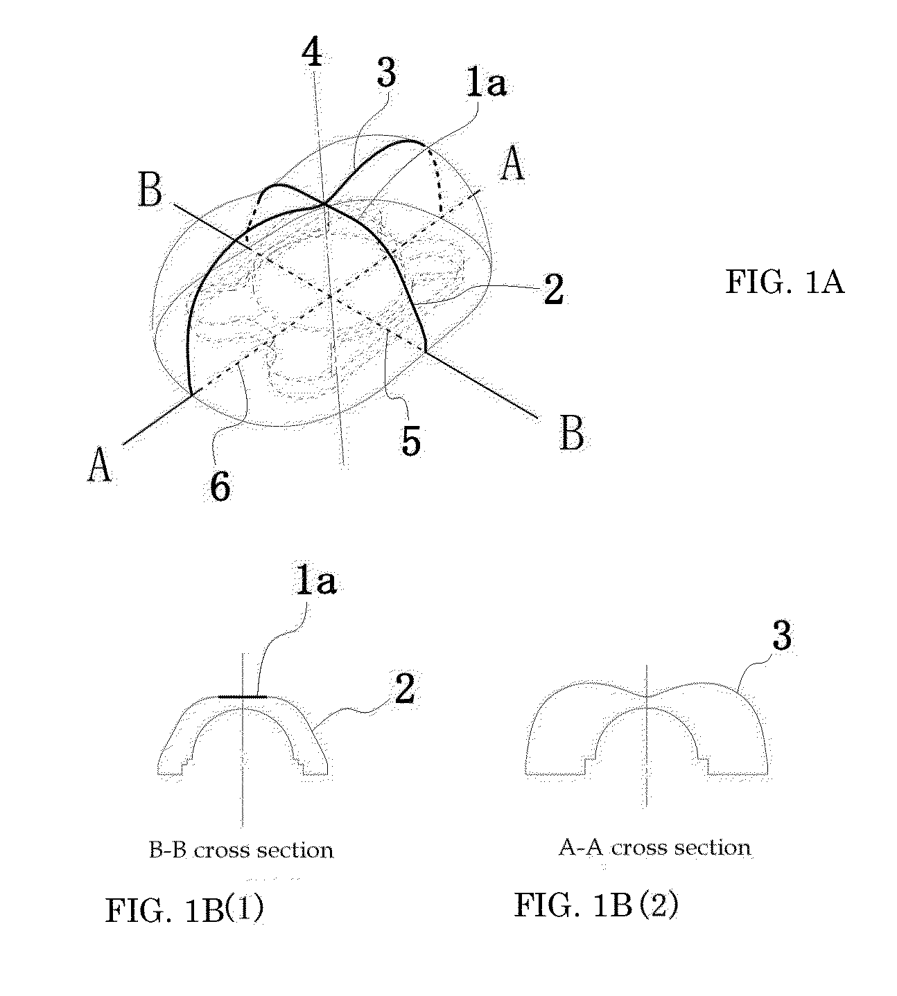
[0077]FIGS. 3A, 3B, 3C(l), 3C(2), 3C(3), and 3C(4) are diagrams showing another example of the lens, according to some embodiments. FIG. 3A shows an oblique perspective figure of the lens, FIG. 3B shows its plan view, FIG. 3C(4) shows the lens long-axis cross section (A-A cross section), FIG. 3C(3) shows the lens short-axis cross section (B-B cross section), and FIGS. 3C(2) and (1) shows the cross sections parallel to the lens short-axis cross section (B1-B1 and B2-B2 cross sections).

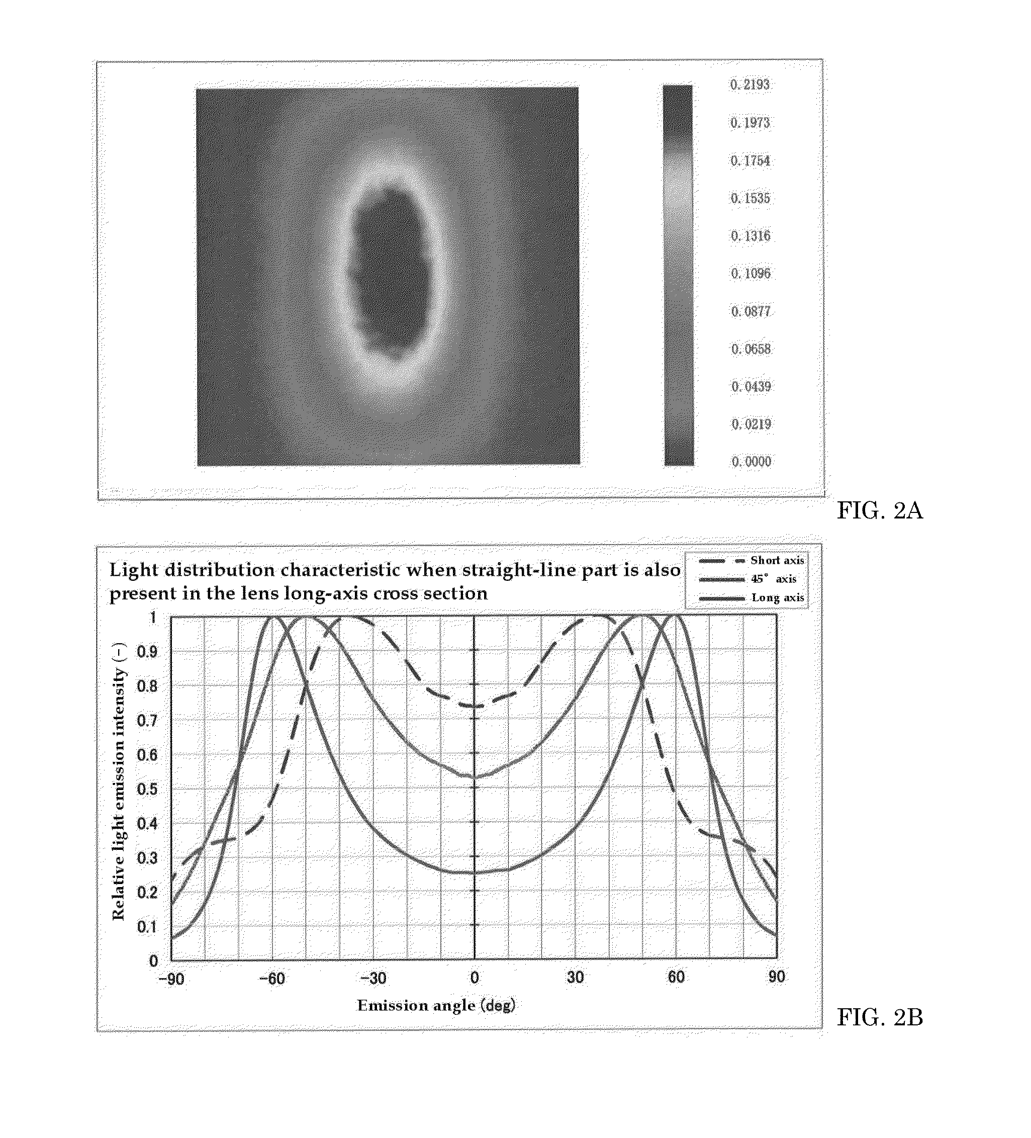
[0078]In the light distribution lens according to the second embodiment of the present invention, as shown in FIGS. 3A, 3B, 3C(1), 3C(2), 3C(3), and 3C(4), the lens surface of the light emitting side has a three-dimensional surface shape, wherein, in a lens cross section taken along a plane parallel to the lens short-axis cross section, the shape has a straight-line part that is parallel to the lens short axis and that intersects with the lens long-axis cross section, and has convex parts at both of its...

third embodiment

[0092]FIGS. 5A(1), 5A(2), 5B(1), 5B(2), and 5B(3) are diagrams showing another example of the lens according to some embodiments. FIGS. 5A(1) and 5A(2) show an oblique perspective figure of the lens, FIG. 5B(1) shows a cross section (B3-B3 cross section) parallel to the lens short-axis cross section (B-B cross section) in FIG. 5A(1), FIG. 5B(2) shows one example of a cross section (B3-B3 cross section) parallel to the lens short-axis cross section (B-B cross section) in FIG. 5B(2), and FIG. 5B(3) shows the lens short-axis cross section (B-B cross section).

[0093]The light distribution lens according to the third embodiment of the present invention is a light distribution lens having, as shown in the oblique perspective figure of FIG. 5A(1), in addition to the continuous curved surface that is formed along the curve of the lens long-axis cross section of the light emitting side and that includes straight lines parallel to the lens short axis, a second curved surface 8b consisting of a...


PUM

PropertyMeasurementUnit
Fractionaaaaaaaaaa
Fractionaaaaaaaaaa
Lengthaaaaaaaaaa

Abstract

A lens for light emitting lamps that use light emitting elements such as LEDs, etc., is provided. The lens has a specific surface shape for light-distribution control to achieve desired light distributions, as well as a light emitting device using said lens. On the lens surface of the light emitting side which has a double-peak shape to obtain a light distribution characteristic having long and short two axes, by possessing a straight-line part in the surface shape of the light emitting side viewed on the lens short-axis cross section, a desired smoothly-diffused light distribution having a longitudinal direction with a certain width is obtained. The lens may be designed to have a surface of the light emitting side comprising a collection of straight lines parallel to the lens short-axis cross section, or to have a continuous curved surface comprising a collection of straight lines parallel to the lens short axis.

Description

CROSS-REFERENCE TO RELATED APPLICATIONS[0001]This application claims the benefit of Japanese Patent Application No. 2014-069186, filed Mar. 28, 2014, which is hereby incorporated by reference in its entirety.BACKGROUND[0002]1. Field of the Invention[0003]The present invention relates to a lens to be provided on a light emitting element lamp, etc. that uses a light emitting element such as an LED.[0004]2. Description of the Related Art[0005]More specifically, the present invention relates to a lens having a specific surface shape for light-distribution control to achieve desired light distribution when the lens is used, the desired light distribution means an elongated and smoothly-diffused light distribution having long and short axes, of the light from a light emitting element which, without said lens, illuminates a surface to be illuminated in a substantially isotropic and rotationally-symmetric manner, and to a light emitting device using such lens as well as a method of manufact...

Claims


Application Information

Patent Timeline
IPC IPC(8): F21V5/04F21K99/00F21V23/00
CPCF21V5/04F21V23/005F21Y2101/02F21K9/90F21K9/50F21Y2115/10G02B19/0014G02B19/0061H01L33/58Y10T29/49144
Inventor MOTOYANAGI, TAKAYUKINAKAMURA, MUNETOMOTASAKI, MASUTSUGUOGURO, HIROKI
Owner NICHIA CORP
Why Eureka
Try Eureka