
Flow actuated flap valve

Inactive Publication Date: 2015-10-01
CAMFIL USA
View PDF11 Cites 5 Cited by
  • Summary
  • Abstract
  • Description
  • Claims
  • Application Information

AI Technical Summary

Benefits of technology

The present invention includes a backdraft damper with a flap valve and a dust collector with the damper. The flap valve prevents pressure waves from propagating upstream of the dust collector. The backdraft damper has a cored damper blade that can lock in a closed position when a pressure wave is detected. The technical effect of this invention is to provide an improved backdraft damper system for controlling air flow and preventing pressure waves from affecting the performance of the dust collector.

Problems solved by technology

The air handling system may include a dust collector to remove small particles from the air in the process environment which may lead to manufacturing defects or present health and safety concerns to the operators.
If such a dust is suspended in air in the right concentration, under certain conditions, it can deflagrate.
Even materials that do not burn in larger pieces (such as aluminum or iron), given the proper conditions, can become explosive in a dust form.
A dust explosion in the dust collection system can travel back via the dirty air plenum and damage connected plant equipment and plant personnel.
Such an explosion if allowed to travel back to the process environment may be catastrophic and even life threatening.
The force from such an explosion can cause employee deaths, injuries, and even destroy entire buildings.
Thus, the dust build-up on the stiffeners changes the dynamics of the blade, i.e., mass which could cause damper to fail when closed by a deflagration.
Additionally, the dust build-up on the stiffeners adds fuel for the propagating flame front to ignite.
However, taking the dust collection system offline often requires that the connected process equipment must also be taken offline, resulting in downtime much more costly than just the cost of the flap valve itself.

Method used


Image

  • Flow actuated flap valve
  • Flow actuated flap valve
  • Flow actuated flap valve

Examples


Embodiment Construction

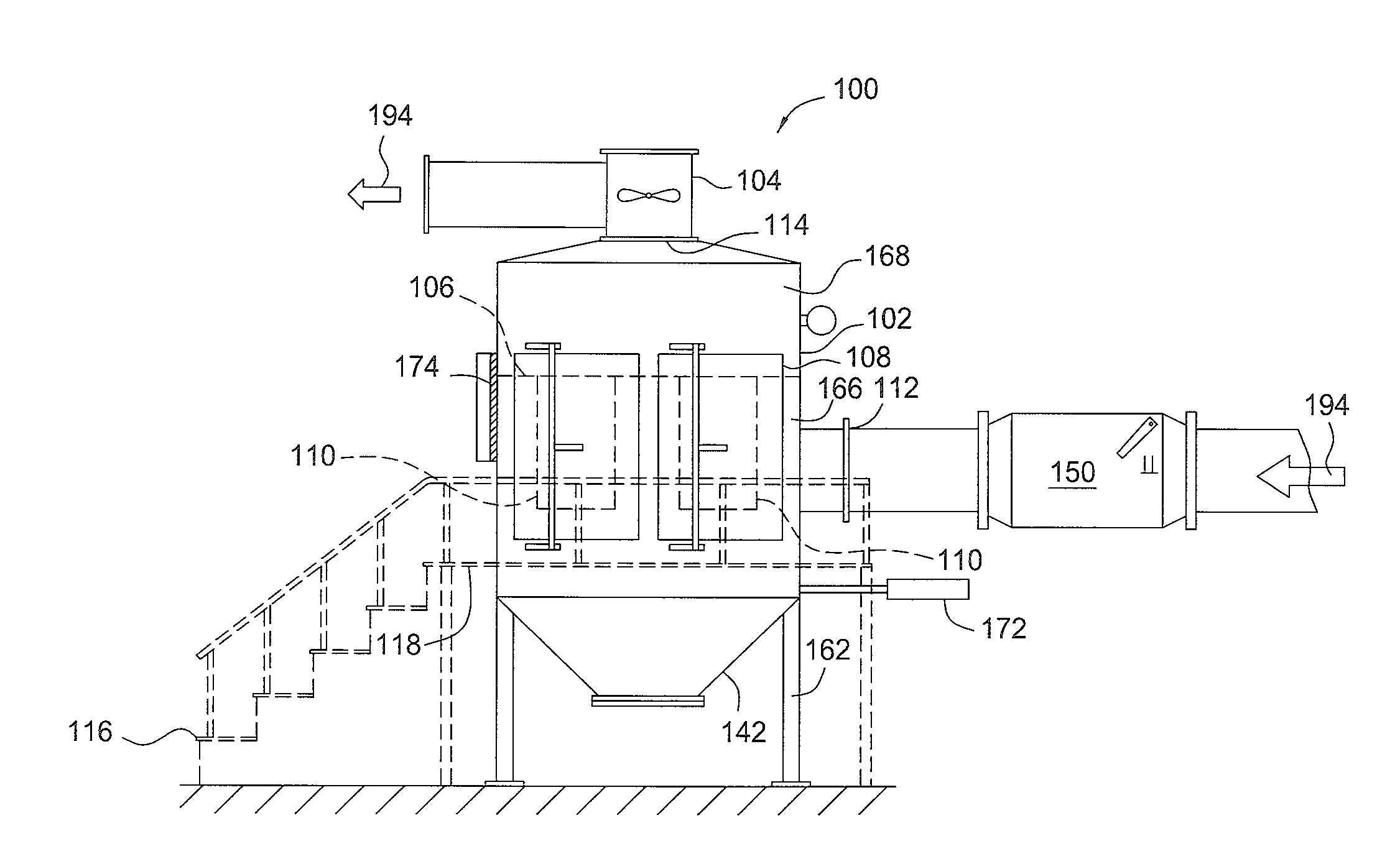
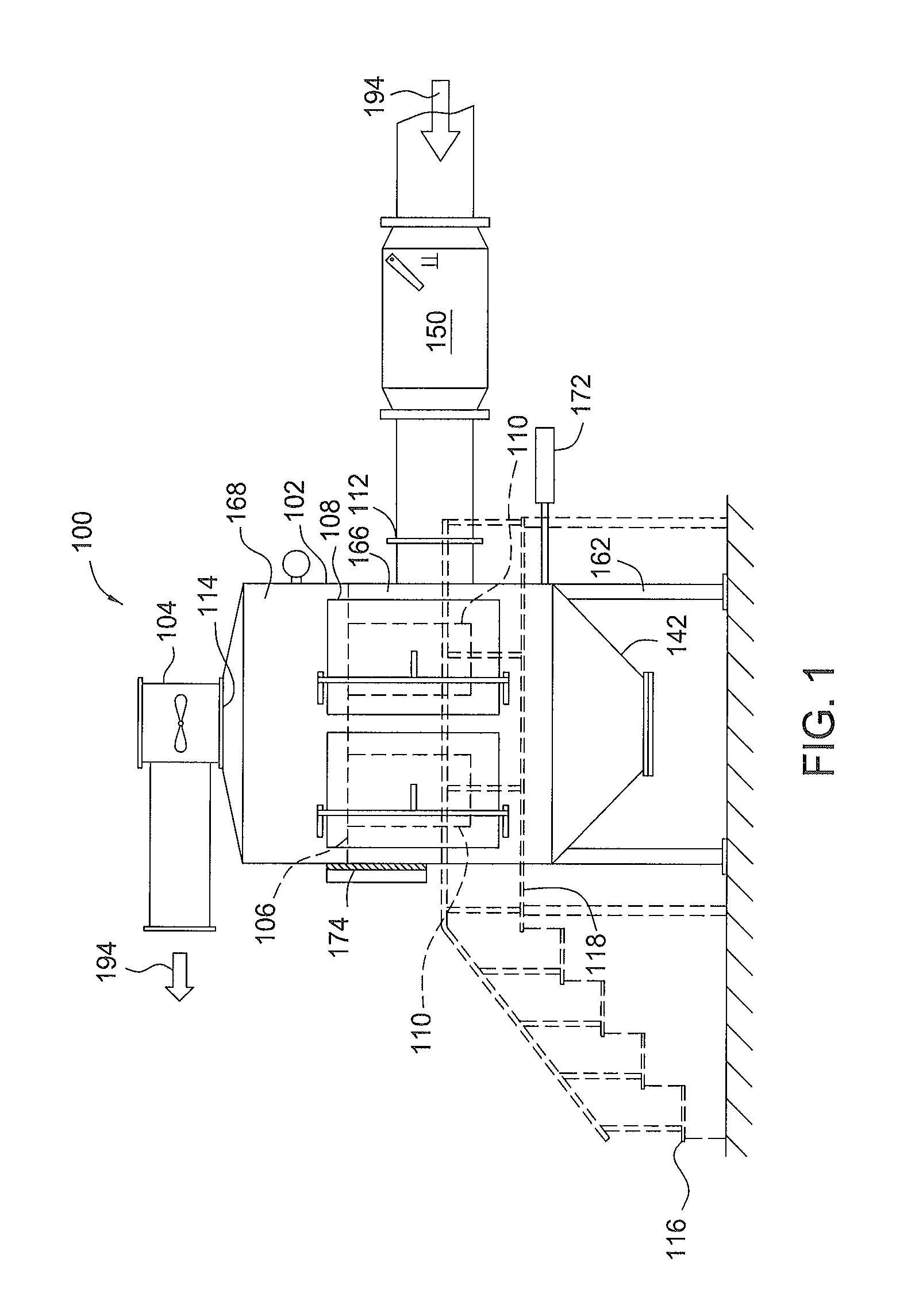
[0022]FIG. 1 is a plan view of one embodiment of a dust collector 100. The dust collector 100 includes a housing 102, and an optional air mover or fan 104. The housing 102 of the dust collector 100 holds at least one replaceable main air filter 110, shown in phantom. The housing 102 has an inlet 112 and an outlet 114. The inlet 112 is coupled to a backdraft damper 150. Although, the exemplary configuration of the dust collector 100 is shown in FIG. 1, it is contemplated that other configurations of dust collectors may be adapted to benefit from the embodiments described herein, including dust collectors of varying designs available from different manufactures.

[0023]The housing 102 is constructed from a rigid material suitable to withstand the operational pressures and loading for which the particular dust collector is designed. The housing 102 is supported by legs 162 and additionally includes at least a main air filter access port (not shown), a main air filter access door 108, a m...


PUM

PropertyMeasurementUnit
Pressureaaaaaaaaaa
Pressureaaaaaaaaaa
Pressureaaaaaaaaaa

Abstract

The present invention generally relates to a backdraft damper having a flap valve, a dust collector having a backdraft damper and a method for preventing a pressure wave from propagating upstream of a dust collector. In one embodiment, a backdraft damper is provided that includes a body having a flap valve disposed therein. The flap valve includes a valve seat disposed in an interior volume of the body. The flap valve includes a blade movable between an open position and a closed position which prevents fluid flow between an inlet and an outlet of the body. The blade of the flap valve includes a core material sandwiched between a first plate and a second plate.

Description

BACKGROUND[0001]1. Field[0002]The present invention relates to an isolation value and in particular, a passive flow activated flap valve for use in an explosive environment.[0003]2. Description of the Related Art[0004]Almost every piece of process equipment in a powder and bulk solid handling plant depends on an engineered air handling system to safely control dust or to reclaim valuable product. The air handling system may include a dust collector to remove small particles from the air in the process environment which may lead to manufacturing defects or present health and safety concerns to the operators. A fan is typically coupled to the dust collector to pull particulate-laden air through a dirty air plenum and through the air filters of the dust collector in order to remove small particles suspended in the process air. In a recirculating dust collection system, the clean air is returned to the process environment through a clean air plenum after moving through the air filters. ...

Claims


Application Information

Patent Timeline
IPC IPC(8): F24F7/08B01D46/42B01D46/00B01D46/48F24F13/14F24F13/28
CPCF24F7/08F24F13/1486F24F13/28B01D46/4227B01D46/48B01D46/4272B01D46/0019F24F11/35
Inventor WALTERS, MICHAEL C.PERSSON, ULFBISOGNI, DOMINICK
Owner CAMFIL USA
Learn More