
Method for the functional extension of an electric welding apparatus and welding apparatus for carrying out the method

a welding apparatus and functional extension technology, applied in the direction of electric programme control, instruments, program control, etc., can solve the problems of software use, authorized users cannot produce copies, and software of this kind cannot be used on an ad hoc basis

Inactive Publication Date: 2015-10-01
LORCH SCHWEISSTECHNIK GMBH
View PDF6 Cites 3 Cited by
  • Summary
  • Abstract
  • Description
  • Claims
  • Application Information

AI Technical Summary

Benefits of technology

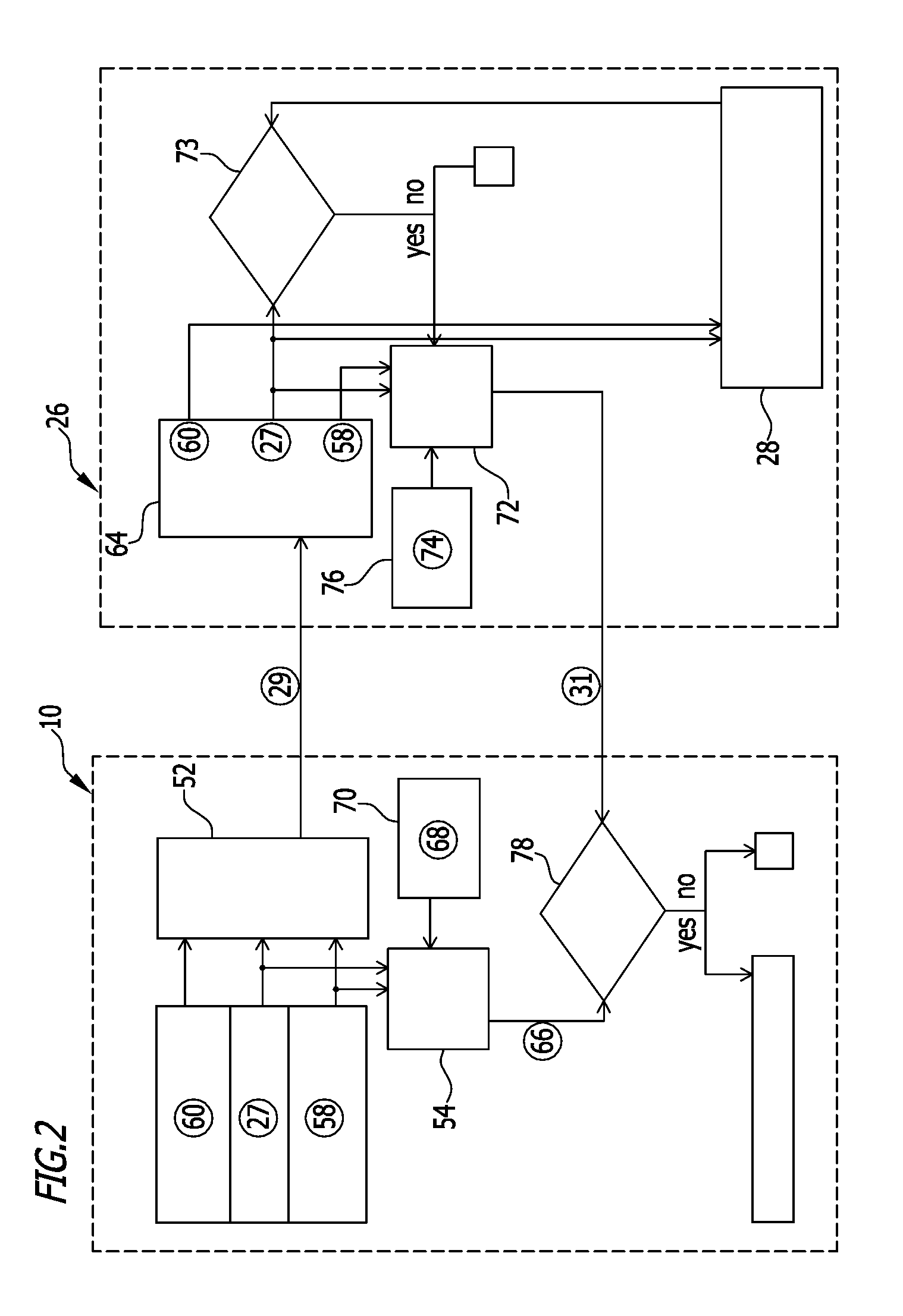
The patent describes a method for controlling a welding apparatus using a control unit. The control unit can issue control commands to activate various functions on the welding apparatus. The control unit generates an apparatus code based on the control command and sends it to an external verifying facility to verify the user's entitlement to the function. The external verifying facility checks the apparatus code and sends an activation code to the control unit to confirm the entitlement. This method allows for easy verification of the user's entitlement without the need for a computer network connection. The identification number of the functional extension is also encoded in the apparatus code, making it easy to identify and activate the desired function.

Problems solved by technology

However, this restricts use of the software to such an extent that even an authorized user cannot produce any copies.
However, an authorized person can pass on the password to unauthorized third parties who are thus in turn able to use the software outside the producer's control.
This gives rise to the difficulty that an authorized user must already be aware of the desired period of activation at the time of purchasing the software, such that software of this kind cannot straightforwardly be used on an ad hoc basis.
This is very troublesome and largely impractical.

Method used


Image

  • Method for the functional extension of an electric welding apparatus and welding apparatus for carrying out the method
  • Method for the functional extension of an electric welding apparatus and welding apparatus for carrying out the method
  • Method for the functional extension of an electric welding apparatus and welding apparatus for carrying out the method

Examples


Embodiment Construction

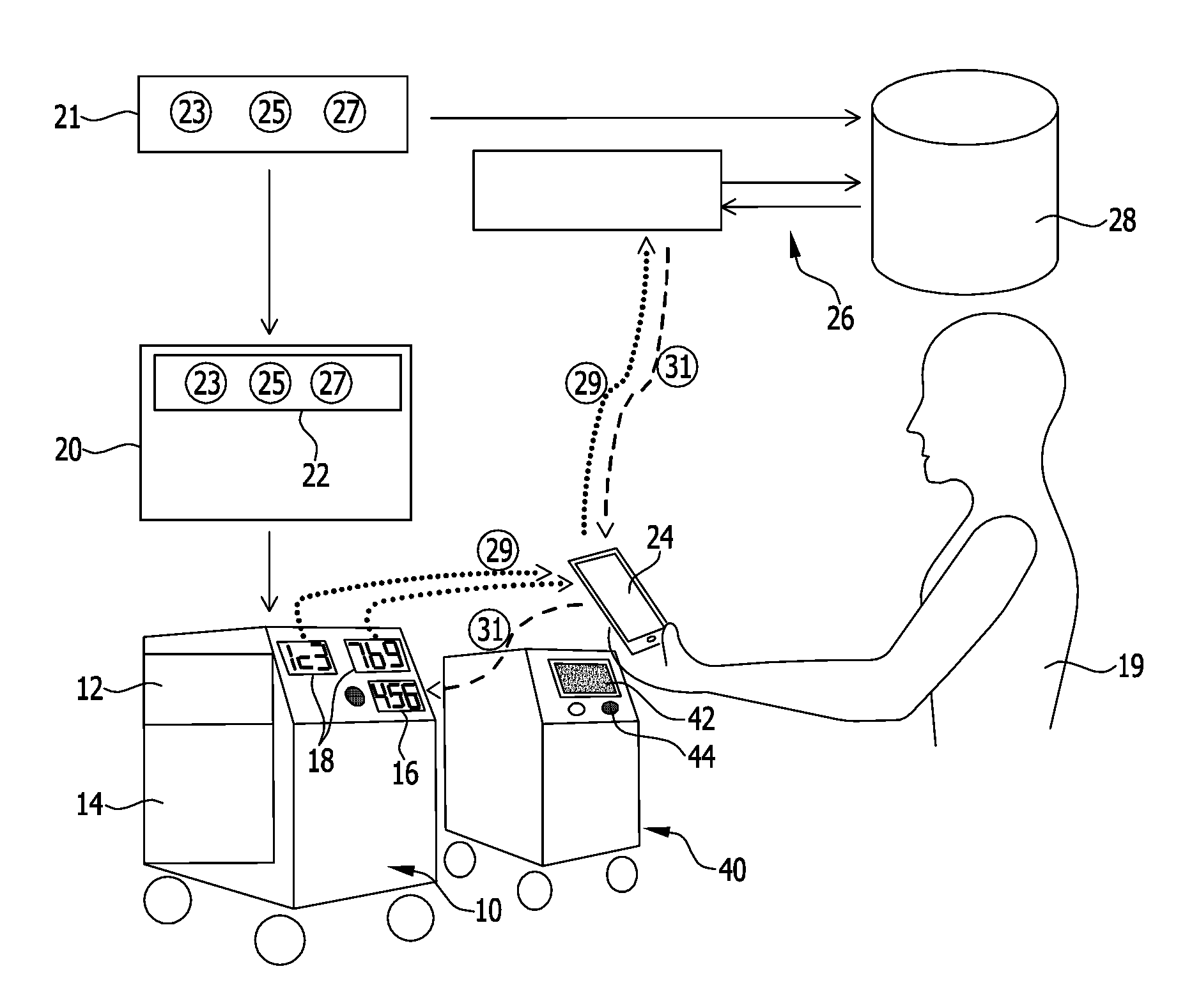
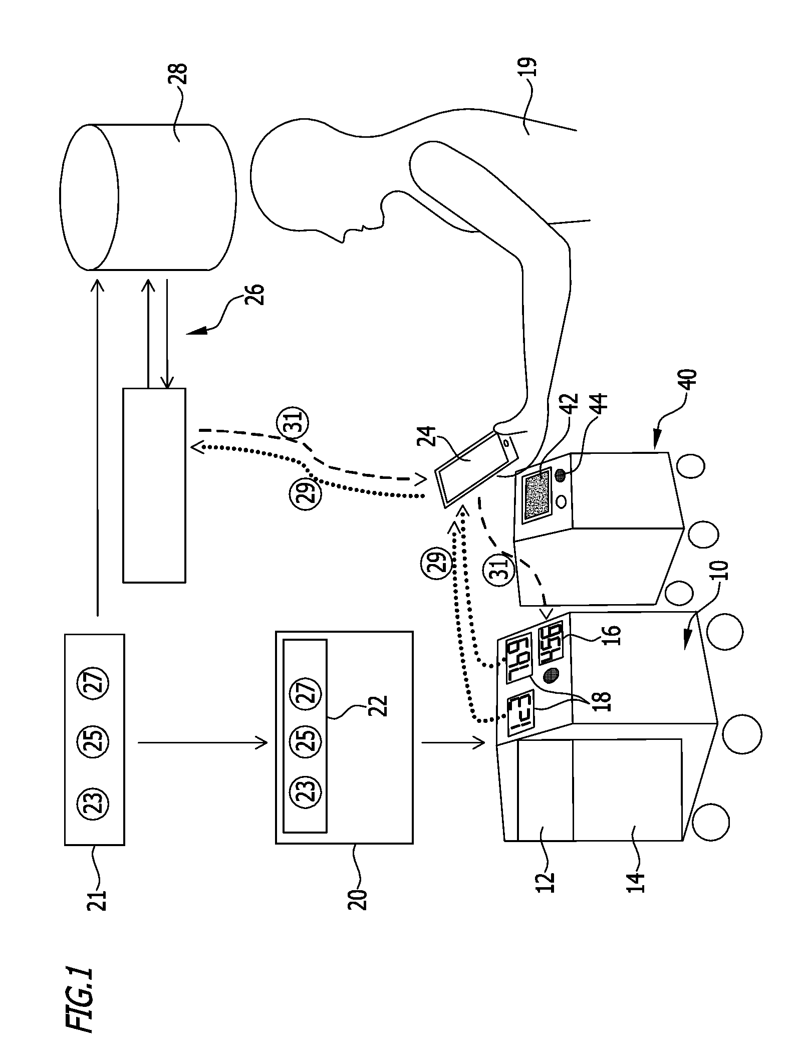
[0049]The drawing is a schematic illustration of a first advantageous embodiment of a welding apparatus according to the invention, designated overall with reference numeral 10. The welding apparatus 10 comprises a control unit 12 and a power supply 14, which is controlled by the control unit 12 and to which a welding torch may conventionally be connected in a manner known per se, for which reason, and to ensure clarity of the drawing, it is not shown. The welding apparatus 10 moreover comprises an input device 16 for inputting control commands and software programs and a display device 18. In the exemplary embodiment shown, the display device 18 comprises a plurality of 7-segment displays.

[0050]Various welding tasks may be performed in conventional manner by a user 19 by means of the welding apparatus 10. The functionality of the welding apparatus 10 may be extended by the user 19. To this end, in the exemplary embodiment shown, the user 19 may purchase a storage medium in the form...


PUM

PropertyMeasurementUnit
timeaaaaaaaaaa
voltageaaaaaaaaaa
currentaaaaaaaaaa

Abstract

A method for extending the functionality of an electric welding apparatus having a programmable control unit and an input device is provided. In order to provide the user with greater latitude for a desired functional extension while nevertheless ensuring that unauthorized functional extension can be prevented, a control command for a desired functional extension is issued to the control unit and the control unit uses the control command or the functional extension to generate an apparatus code which is transmitted to an external verifying facility. The external verifying facility uses the apparatus code to verify entitlement to the functional extension and, if entitlement exists, generates an external activation code which is transmitted to the control unit. The control unit then verifies the validity of the external activation code and, if it is valid, implements the functional extension. A welding apparatus for carrying out the method is also proposed.

Description

[0001]This application claims the benefit of German application number 10 2014 104 227.1 filed on Mar. 26, 2014, which is incorporated herein by reference in its entirety and for all purposes.BACKGROUND OF THE INVENTION[0002]The invention relates to a method for extending the functionality of an electric welding apparatus which comprises a programmable control unit and an input device.[0003]The invention moreover relates to an electric welding apparatus for carrying out the method, the welding apparatus comprising a programmable control unit and the functionality of the welding apparatus being extendable, and the welding apparatus comprising an input device.[0004]Electric welding apparatuses for electric welding of a workpiece conventionally comprise a control unit, a power supply and a welding torch with a welding electrode connectable to the power supply. Between the welding electrode and the workpiece to be welded, an arc is generated, the action of which produces a weld seam. Th...

Claims


Application Information

Patent Timeline
Patent Type & Authority Applications(United States)
IPC IPC(8): G05B19/042
CPCG05B2219/45135G05B19/0426B23K9/1062G06F8/65G05B2219/23298
Inventor GOEPPERT, JOSEF
Owner LORCH SCHWEISSTECHNIK GMBH
Learn More