Time-Varying Extremum Seeking for Controlling Vapor Compression Systems

a technology of vapor compression system and extremum, which is applied in the direction of lighting and heating apparatus, heating types, instruments, etc., can solve the problems of single model not being able to accurately describe the variations among copies produced as the result of a manufacturing process, the model of the system deviating from the actual behavior of the system, and the different amounts of energy consumed. achieve the effect of optimizing or minimizing the signal, improving the convergence rate of extremum-seeking control methods

Active Publication Date: 2015-10-01
MITSUBISHI ELECTRIC RES LAB INC
View PDF5 Cites 21 Cited by
  • Summary
  • Abstract
  • Description
  • Claims
  • Application Information

AI Technical Summary

Benefits of technology

[0016]One object of some embodiments of the invention is to improve a rate of convergence of extremum-seeking control methods that maximize or minimize a signal representing a metric of performance of vapor compression systems. Optimizing the metric of performance requires an estimate of a parameter representing a relationship between values of the control signal and values of the metric of performance.

Problems solved by technology

A combination of commanded inputs to the vapor compression system that delivers a particular amount of heat is often not unique and these various combinations consume different amounts of energy.
However, the use of mathematical models for the selection of optimizing inputs has several important drawbacks.
These assumptions often ignore important effects or do not consider installation-specific characteristics such as room size, causing the model of the system to deviate from actual behavior of the system.
Secondly, the variation in those systems during the manufacturing process are often so large as to produce vapor compression systems of the same type that exhibit different input-output characteristics, and therefore a single model cannot accurately describe the variations among copies produced as the outcome of a manufacturing process.
Thirdly, those models are difficult to derive and calibrate.
Determining the values of these parameters for each model is an extensive effort.
A model that accurately descr

Method used


Image

  • Time-Varying Extremum Seeking for Controlling Vapor Compression Systems
  • Time-Varying Extremum Seeking for Controlling Vapor Compression Systems
  • Time-Varying Extremum Seeking for Controlling Vapor Compression Systems

Examples


example

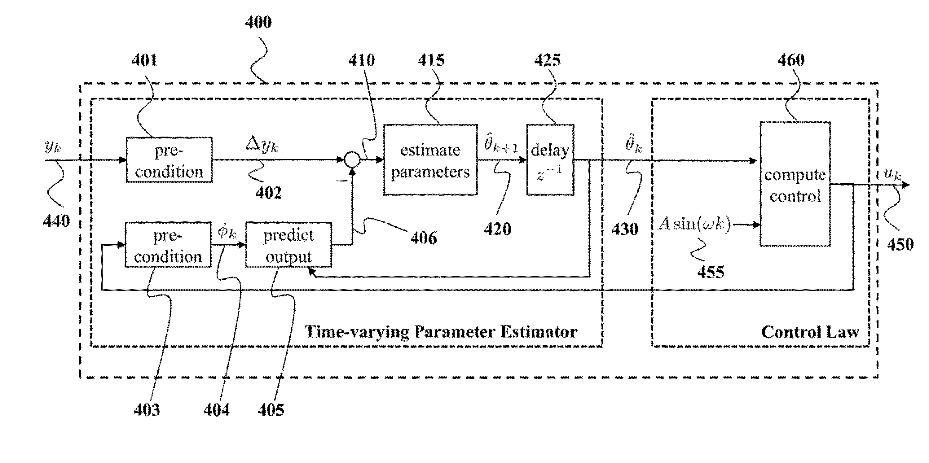
[0094]FIG. 7A shows a schematic of usage of an extremum seeking method for the problem of minimizing the performance metric of a simple Hammerstein system 730 including a first-order linear difference equation 720 and a static output nonlinearity 725. The controller 710 generates control signal 701 provided to the optimization target 730 and receives measurements of the performance metric 703. The controller has no model of the Hammerstein system or any explicit knowledge about the nature of its optimal value, other than the assumption that the relationship between the input and output is convex, and that the optimal value of the performance metric, y 703 is a minimum.

[0095]The equations for this system 730 are given by

xk+1=0.8xk+uk

yk=(xk−3)2+1

which has a single optimum point at

u*=0.6

y*=1.

[0096]FIGS. 7B and 7C show graphs representing a comparison of the performance of the controller 710 starting from an initial input value of u=2 and turned ON after 100 steps. The conventional con...


PUM


Abstract

A method for controlling a vapor compression system determines a value of a metric of performance of the vapor compression system using a previous value of an estimated parameter and a previous value of a control signal determined for a previous time step of the control. The values of the estimated parameter represent a relationship between values of the control signal and values of the metric of performance. A current value of the estimated parameter is determined based on the previous value of the estimated parameter and an error between the determined value of the metric of performance and a measured value of the metric of performance. Next, a current value of the control signal is determined based on the current value of the estimated parameter.

Description

FIELD OF THE INVENTION[0001]This invention pertains to the field of controls for vapor compression systems, and more particularly, to control methods for optimizing a performance metric of the vapor compression systems.BACKGROUND OF THE INVENTION[0002]Vapor compression systems, such as heat pumps, refrigeration and air-conditioning systems, are widely used in industrial and residential applications. The introduction of variable speed compressors, variable position valves, and variable speed fans for the vapor compression cycle has greatly improved the flexibility of the operation of such systems. It is possible to improve the efficiency of vapor compression systems by controlling these new components correctly.[0003]For example, a speed of the compressor can be adjusted to modulate a flow rate of a refrigerant. The speed of an evaporator fan and a condenser fan can be varied to alter heat transfer between air and heat exchangers. The change in an expansion valve opening can directly...

Claims


Application Information

Patent Timeline
IPC IPC(8): G05D7/06G06F11/07G05B15/02
CPCG05D7/0629G06F11/079G05B15/02F25B49/02F24F11/49F24F11/64F24F11/30F24F2110/00Y02B30/70G01D3/028
Inventor BURNS, DANIELGUAY, MARTINWEISS, WALTER
Owner MITSUBISHI ELECTRIC RES LAB INC
Why Eureka
Try Eureka