Fail-safe apparatus for inverter

a failure-safe, inverter technology, applied in the direction of motor/generator/converter stopper, dynamo-electric converter control, stopping arrangement, etc., can solve the problem that the inverter cannot be controlled the induction voltage produced by the rotation of the motor becomes excessively high, and the inverter cannot be controlled to be in the three-phase short-circuit mode. to achieve the effect of suppressing the dc power sour

Active Publication Date: 2015-10-01
MITSUBISHI ELECTRIC CORP
View PDF8 Cites 16 Cited by
  • Summary
  • Abstract
  • Description
  • Claims
  • Application Information

AI Technical Summary

Benefits of technology

[0011]In the present invention, although a motor is PWM-driven at normal time, a three-phase switching device is switched from PWM driving to three-phase short-circuiting driving when some sort of abnormality

Problems solved by technology

However, in the case of such a motor, as described above, that utilizes a permanent magnet for producing a magnetic field and operates at a high rotation speed, when an abnormality occurs in the inverter at a time when the motor rotates at a high rotation speed, the induction voltage produced by the rotation of the motor becomes excessively high; thus, the excessively high voltage may break the inverter; in addition, for example, in the case of a 48-V system, the induction voltage exceeds the upper limit voltage of the DC power source and hence the vol

Method used


Image

  • Fail-safe apparatus for inverter
  • Fail-safe apparatus for inverter
  • Fail-safe apparatus for inverter

Examples


embodiment 1

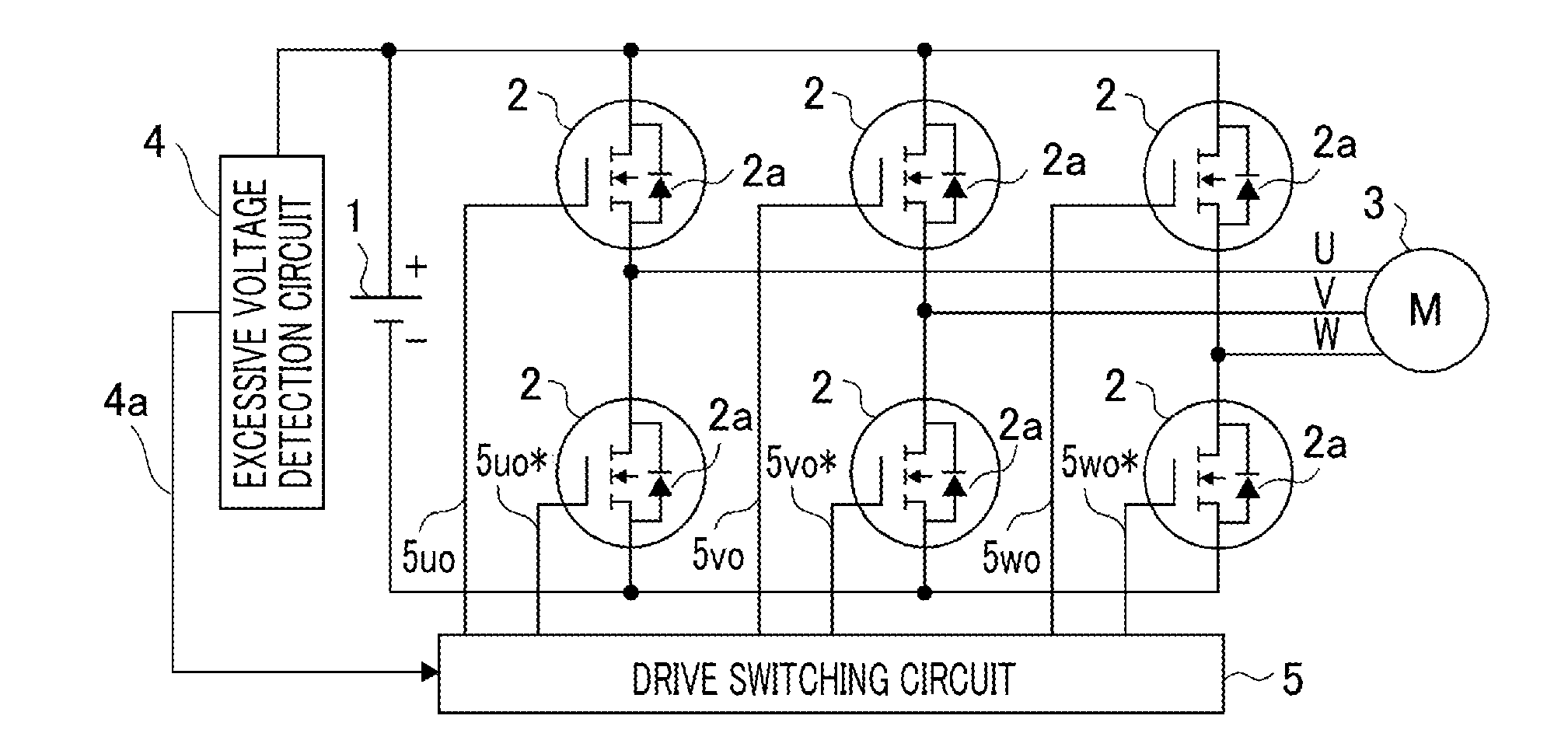
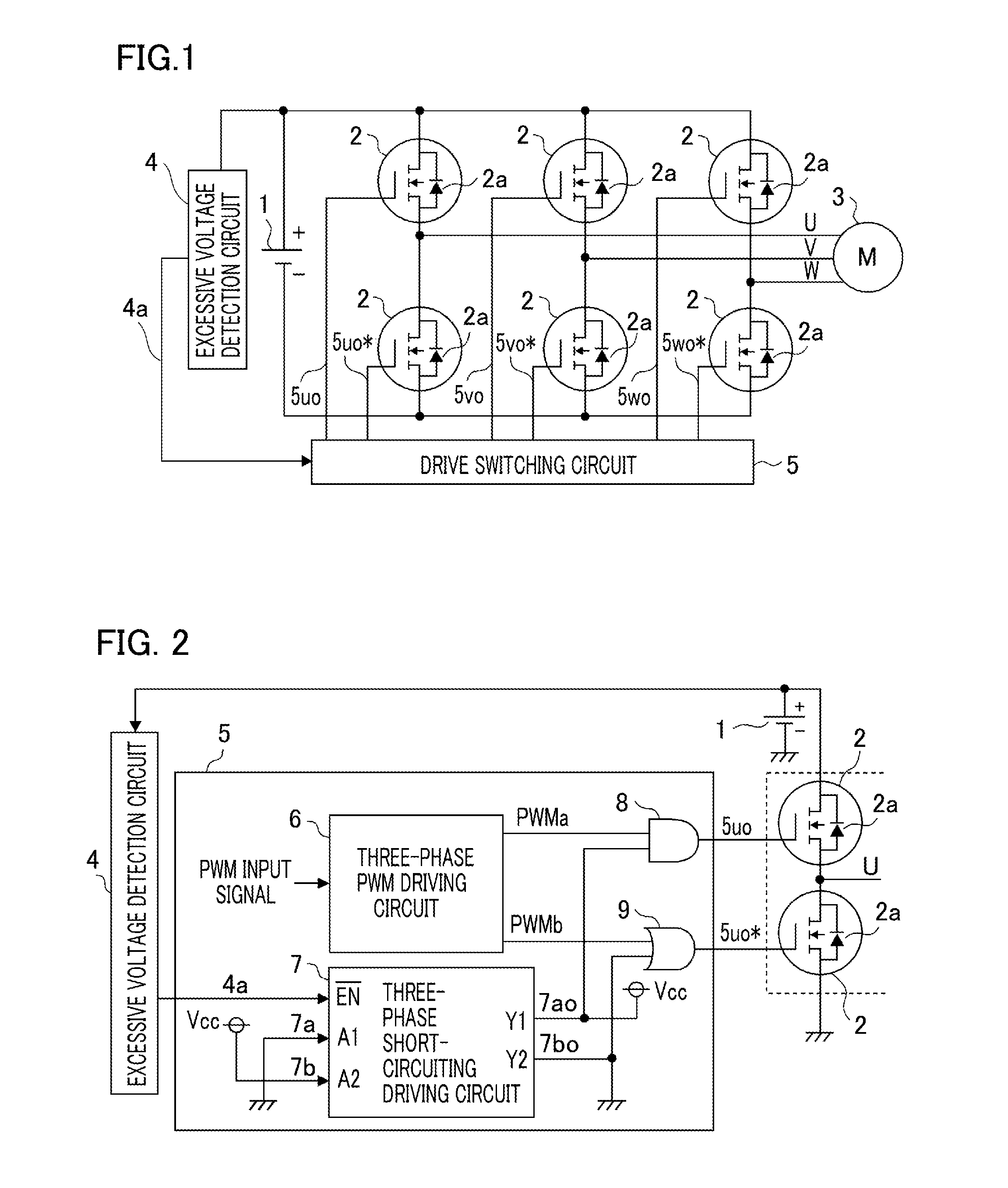
[0021]FIG. 1 illustrates an example of a fail-safe apparatus according for an inverter to Embodiment 1 of the present invention. This inverter has a switching circuit configured with a semiconductor switching device 2 such as an IGBT (Insulated Gate Bipolar Transistor) or a MOSFET (Metal Oxide Semiconductor Field Effect Transistor), performs PWM drive of a DC voltage supplied from a DC power source 1, by use of the semiconductor switching device 2, and converts the DC voltage into a three-phase AC voltage so as to drive a synchronous motor (referred to also as a motor, hereinafter) 3.

[0022]For example, the motor 3 is directly connected with an engine or is belt-connected with an engine through a pulley or the like. In the case where the motor 3 is rotated by the engine, the inverter can be operated as an electric power generator; when the induction voltage of the motor 3 is larger than the DC power source voltage of the inverter, PWM drive utilizing the rectification action of a ref...

embodiment 2

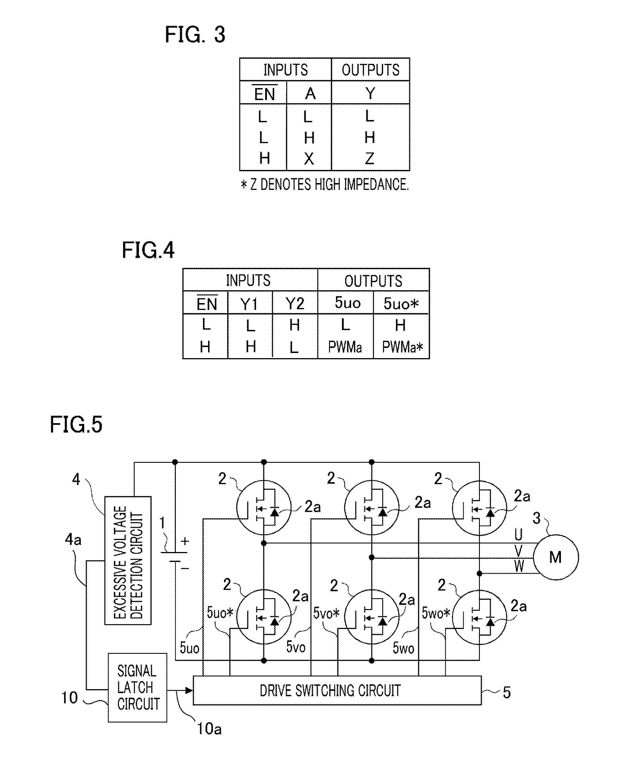
[0030]FIG. 5 illustrates an example of a fail-safe apparatus for an inverter according to Embodiment 2 of the present invention. The same constituent elements as those in Embodiment 1 are designated by the same reference characters.

[0031]Embodiment 2 differs from Embodiment 1 in that Embodiment 2 has a signal latch circuit 10 for latching the excessive voltage determination signal 4a between the excessive voltage detection circuit 4 and the drive switching circuit 5.

[0032]In response to the input of an falling edge of the excessive voltage determination signal 4a outputted from the excessive voltage detection circuit 4, the signal latch circuit 10 latches an excessive voltage determination latch signal 10a, which is an output signal thereof, to “L”. The excessive voltage determination latch signal 10a outputted from the signal latch circuit 10 is inputted to the drive switching circuit 5. In other words, the excessive voltage determination latch signal 10a is inputted to the input E...

embodiment 3

[0036]FIG. 7 illustrates the configuration of a fail-safe apparatus for an inverter according to Embodiment 3 of the present invention. The same constituent elements as those in Embodiment 1 are designated by the same reference characters.

[0037]Embodiment 3 differs from each of Embodiments 1 and 2 in that Embodiment 3 has a control circuit 11 for releasing a latched signal in addition to Embodiment 2. As the control circuit 11, for example, a microcomputer or the like is utilized.

[0038]Next, the operation of the fail-safe apparatus for the inverter according to Embodiment 3 of the present invention will be explained. The voltage of the DC power source 1 is detected by the excessive voltage detection circuit 4; then, the excessive voltage determination signal 4a outputted by the excessive voltage detection circuit 4 is inputted to the signal latch circuit 10 and the control circuit 11. Once an excessive voltage is detected and hence the excessive voltage determination signal 4a becom...


PUM


Abstract

There is provided a fail-safe apparatus for an inverter that can suppress the voltage of a DC power source from rising when the voltage of the DC power source becomes excessive, due to an abnormality caused in an inverter that performs driving and electric-power generation by use of a synchronous motor in which a permanent magnet is utilized as a magnetic-field magnet. The fail-safe apparatus for the inverter includes an excessive voltage detection circuit for detecting a state of excessive voltage while monitoring the voltage of the DC power source of the inverter and a drive switching circuit for switching a driving method for a semiconductor switching device between three-phase PWM driving and three-phase short-circuiting driving in accordance with the state of an excessive voltage detection circuit.

Description

BACKGROUND OF THE INVENTION[0001]1. Field of the Invention[0002]The present invention relates to a fail-safe apparatus for an inverter.[0003]2. Description of the Related Art[0004]In recent years, due to the tendency toward gasoline mileage regulation on automobiles, a mild-hybrid automobile and the like have been put to practical use; For example, a synchronous motor equipped with an inverter is utilized in such a hybrid automobile. In addition, due to a demand for a high-power motor and the like, a system utilizing a new DC power source such as a 48-V battery or a 48-V lithium ion battery has been drawing attention, in comparison with a system utilizing 12-V battery DC power source. The foregoing synchronous motor includes a synchronous motor that utilizes a permanent magnet for producing a magnetic field and operates at a high rotation speed. While such a synchronous motor equipped with a permanent magnet does not require any excitation current, the induction voltage produced by ...

Claims


Application Information

Patent Timeline
IPC IPC(8): H02P6/12H02P6/24
CPCH02P6/24H02P6/12H02M1/32H02M7/5387
Inventor SOTOME, HIDEYUKI
Owner MITSUBISHI ELECTRIC CORP
Why Eureka
Try Eureka