Glass-wiping robot having air-venting device

a technology of air venting device and glass-wiping robot, which is applied in the field of small household electrical appliances, can solve the problems of affecting the work efficiency of glass-wiping robot, and achieve the effects of improving work efficiency, simple structure, and reducing labor intensity

Active Publication Date: 2015-10-08
ECOVACS ROBOTICS (SUZHOU ) CO LTD
View PDF2 Cites 14 Cited by
  • Summary
  • Abstract
  • Description
  • Claims
  • Application Information

AI Technical Summary

Benefits of technology

[0003]In view of the above deficiencies in the prior art, the present invention provides a glass-wiping robot having an air-venting device, wherein after a handle of an air-venting valve is pulled up, a positioning rotary shaft rotates to trigger the air-venting valve, and then the air-venting valve opens an air-venting hole therein to allow the interior of the suction cup to be in communication with the atmosphere, thus an equilibrium between internal and external air pressures is achieved rapidly, and the glass-wiping robot can be removed rapidly without having to wait. Accordingly, the glass-wiping robot having an air-venting device has a simple structure and an improved work efficiency.
[0009]As described above, in the present invention, the air-venting device is disposed on the airway pipe which connects the vacuum air pump and the suction cup device so that when the handle of the air-venting valve is pulled up, the positioning rotary shaft rotates to trigger the air-venting valve, and the air-venting valve opens an air-venting hole therein to allow the interior of the suction cup to be in communication with the atmosphere, thus an equilibrium between internal and external air pressures is achieved rapidly, and the glass-wiping robot can be removed rapidly without having to wait. Thus, the work efficiency is increased.

Problems solved by technology

Upon the completion of the cleaning work, the vacuum pump stops, and the glass-wiping robot has to wait to be removed from the glass surface until the suction cup loses efficacy naturally.
This process generally takes a certain period of time, and thus greatly effects the work efficiency of the glass-wiping robot.

Method used


Image

  • Glass-wiping robot having air-venting device
  • Glass-wiping robot having air-venting device
  • Glass-wiping robot having air-venting device

Examples


Embodiment Construction

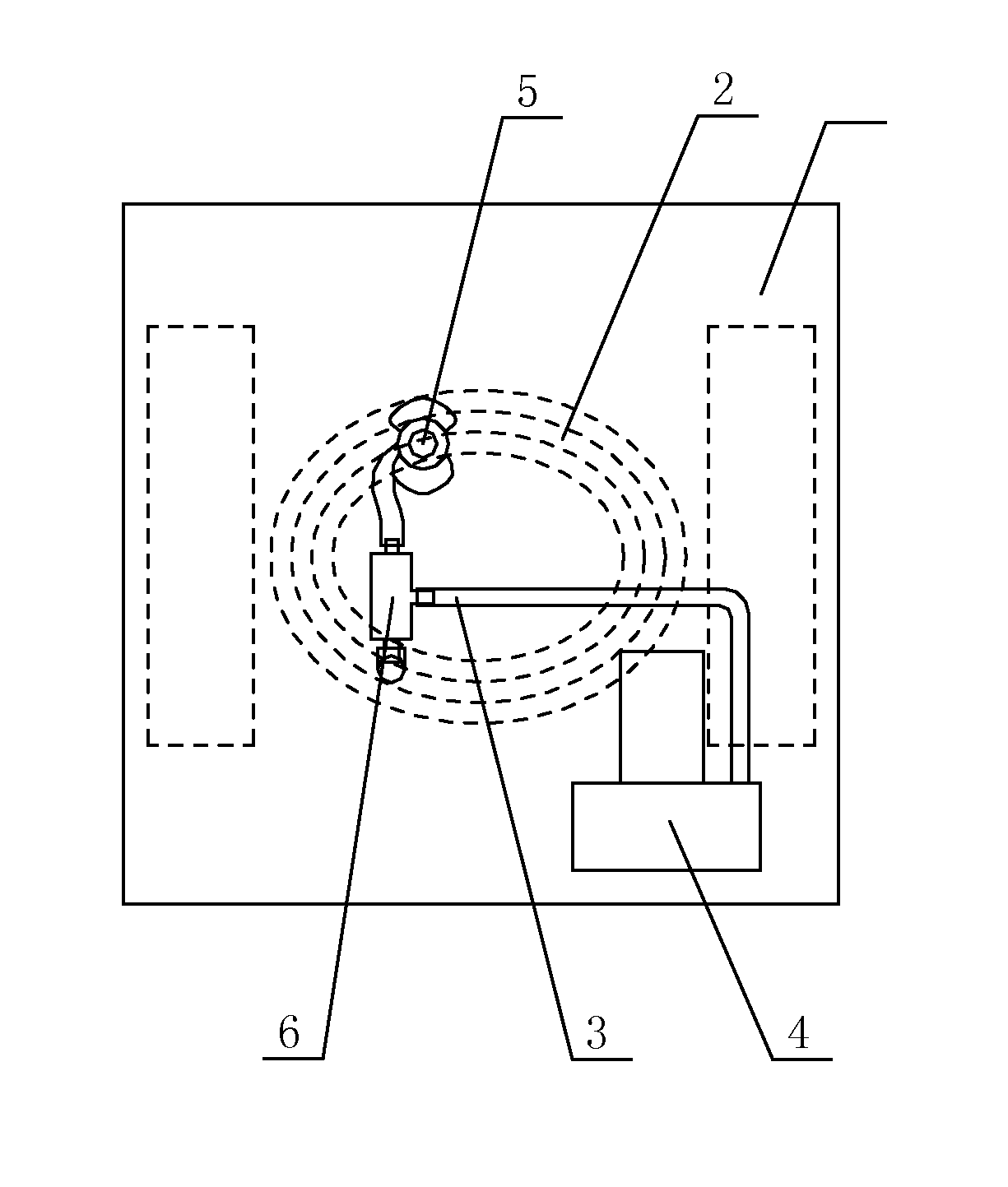
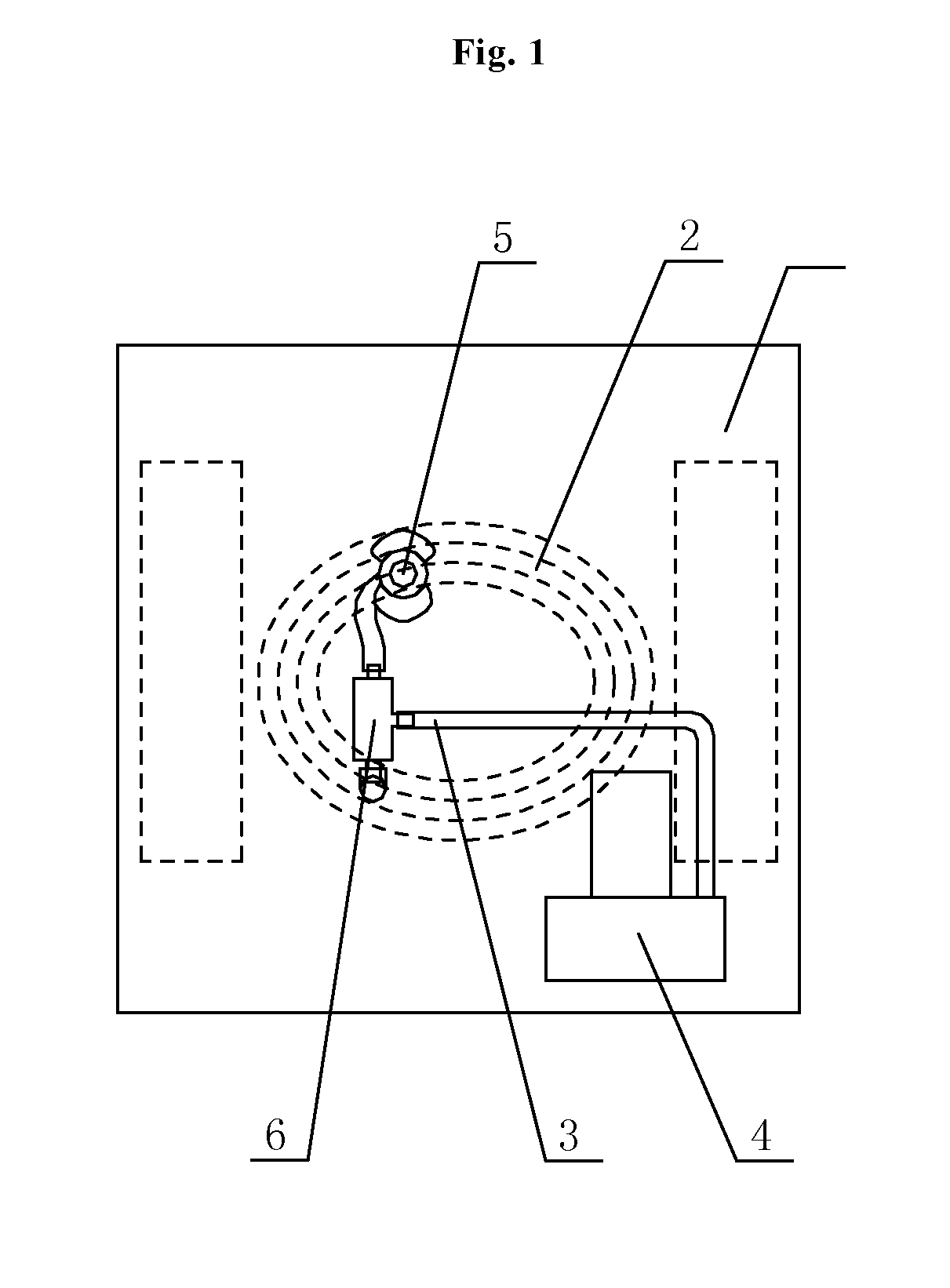
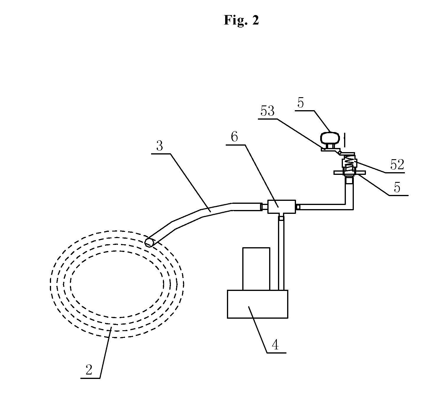
[0014]FIG. 1 is a schematic diagram of the overall structure of the present invention, and FIG. 2 is a schematic diagram of the partial structure of FIG. 1. As shown in FIG. 1 in combination with FIG. 2, a glass-wiping robot having an air-venting device according to the present invention comprises a machine body 1 on which a suction cup device 2 is provided. The suction cup device 2 is connected to a vacuum air pump 4 via an airway pipe 3, and the glass-wiping robot is adsorbed on a glass surface through the suction cup device 2. The suction cup device 2 is also connected to an air-venting device 5 provided with opened and closed positions. When the air-venting device 5 is at the opened position, the suction cup device 2 is in communication with the atmosphere via the air-venting device 5. The air-venting device 5 is disposed on the airway pipe 3 which connects the vacuum air pump 4 and the suction cup device 2. To facilitate the connection, the suction cup device 2, the vacuum air ...


PUM


Abstract

A glass-wiping robot having an air-venting device (b 5), comprising a machine body (b 1). The machine body (b 1) has arranged thereon a suction cup device (b 2). The suction cup device (b 2) is connected to a vacuum air pump (b 4) via an airway pipe (b 3). The glass-wiping robot is adsorbed on a surface of a glass via the suction cup device (b 2). The suction cup device (b 2) is also connected to an air-venting device (b 5). The air-venting device (b 5) is provided with opened and closed positions. When the air-venting device (b 5) is at the opened position, the suction cup device (b 2) is in communication with the atmosphere via the air-venting device (b 5). The glass-wiping robot has the air-venting device (b 5) arranged on the airway pipe (b 3) between the vacuum air pump (b 4) and the suction cup device (b 2), wherein when a handle (b 51) is pulled up, a positioning rotary shaft (b 53) rotates to trigger an air-venting valve (b 52), and the air-venting valve (b 52) opens an air-venting hole therein to allow the interior of the suction cup to be in communication with the atmosphere, thus an equilibrium between internal and external air pressures is achieved rapidly, the glass-wiping robot can be removed rapidly without having to wait, and the work efficiency is increased.

Description

FIELD OF THE INVENTION[0001]The present invention relates to a glass-wiping robot having an air-venting device, which belongs to the technical field of small household electrical appliances.BACKGROUND OF THE PRIOR ART[0002]The glass-wiping robot has been widely used owing to its characteristics of compact size and flexible movement. The existing glass-wiping robot (also referred to as “Winbot”) moves under the driving of a walking mechanism provided on the machine body, as it is adsorbed on the surface of a glass to be cleaned after a suction cup provided on the machine body is vacuumized by a vacuum pump, so as to conduct a cleaning work on the surface of the glass to be cleaned. Upon the completion of the cleaning work, the vacuum pump stops, and the glass-wiping robot has to wait to be removed from the glass surface until the suction cup loses efficacy naturally. This process generally takes a certain period of time, and thus greatly effects the work efficiency of the glass-wipin...

Claims


Application Information

Patent Timeline
Patent Type & Authority Applications(United States)
IPC IPC(8): A47L1/02B08B1/00
CPCB08B1/006A47L1/02A47L2201/00B62D57/024F16B47/00A47L11/38
Inventor LV, XIAOMING
Owner ECOVACS ROBOTICS (SUZHOU ) CO LTD
Why Eureka
Try Eureka