Method and System for Controlling Electrical Conditions of Tissue II

a technology of electrical conditions and tissue, applied in the field of tissue electrical conditions control, can solve the problems of difficult task, presenting a significant obstacle to isolating the cap of interest, and the precise mechanisms involved are poorly understood, so as to reduce the complexity of the measurement signal chain, reduce the interaction, and reduce the effect of artefa

Inactive Publication Date: 2015-10-08
SALUDA MEDICAL PTY LTD
View PDF13 Cites 59 Cited by
  • Summary
  • Abstract
  • Description
  • Claims
  • Application Information

AI Technical Summary

Benefits of technology

[0030]Preferred embodiments of the invention may thus reduce artefact by reducing interaction between the stimulus and the measurement recording via a measurement amplifier input capacitance.
[0031]Some embodiments of the invention may utilise a blanking circuit for blanking the measurement

Problems solved by technology

While the clinical effect of spinal cord stimulation (SCS) is well established, the precise mechanisms involved are poorly understood.
However, this can be a difficult task as an observed CAP signal will typically have a maximum amplitude in the range of microvolts, whereas a stimulus applied to evoke the CAP is typically several volts.
Electrode artefact usually results from the stimulus, and manifests as a decaying output of several millivolts throughout the time that the CAP occurs, presenting a significant obstacle to isolating the CAP of interest.
The capacitor recovers charge at the highest rate immediately after the stimulus, undesirably causing greatest artefact at the same time that the evoked response occurs.
To resolve a 10 uV SCP with 1 uV resolution in the presence of an input 5V stimulus, for example, requires an amplifier with a dynamic range of 134 dB, which is impractical in implant systems.
As the neural response can be contemporaneous with the stimulus and/or the stimulus artefact, CAP measurements present a difficult challenge of amplifier design.
In p

Method used


Image

  • Method and System for Controlling Electrical Conditions of Tissue II
  • Method and System for Controlling Electrical Conditions of Tissue II
  • Method and System for Controlling Electrical Conditions of Tissue II

Examples


Embodiment Construction

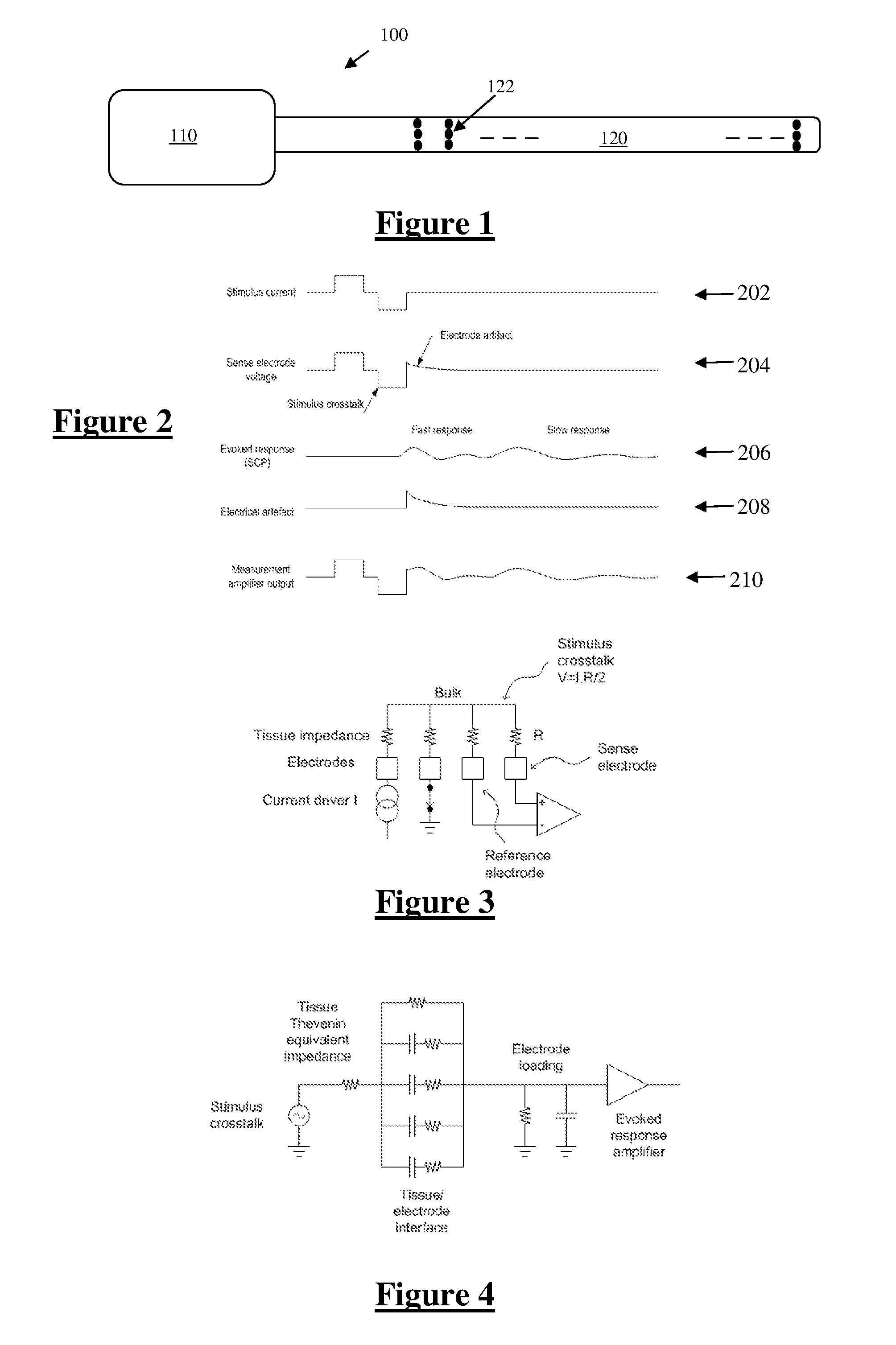
[0050]FIG. 1 illustrates an implantable device 100 suitable for implementing the present invention. Device 100 comprises an implanted control unit 110, which controls application of a sequence of neural stimuli. In this embodiment the unit 110 is also configured to control a measurement process for obtaining a measurement of a neural response evoked by a single stimulus delivered by one or more of the electrodes 122. Device 100 further comprises an electrode array 120 consisting of a three by eight array of electrodes 122, each of which may be selectively used as the stimulus electrode, sense electrode, compensation electrode or sense electrode.

[0051]FIG. 2 shows the currents and voltages that contribute to spinal cord potential (SCP) measurements in a typical system of the type shown in FIG. 3. These signals include the stimulus current 202 applied by two stimulus electrodes, which is a charge-balanced biphasic pulse to avoid net charge transfer to or from the tissue and to provide...


PUM


Abstract

A method for controlling electrical conditions of tissue in relation to a current stimulus. A first current produced by a first current source is delivered to the tissue via a current injection electrode. A second current drawn by a second current source is extracted from the tissue via a current extraction electrode. The second current source is matched with the first current source so as to balance the first current and the second current. A ground electrode which is proximal to the current injection electrode and the current extraction electrode is grounded, to provide a ground path for any mismatch current between the first current and second current. A response of the tissue to the current stimulus is measured via at least one measurement electrode.

Description

CROSS-REFERENCE TO RELATED APPLICATIONS[0001]This application claims the benefit of Australian Provisional Patent Application No. 2012904838 filed 6 Nov. 2012, which is incorporated herein by reference.TECHNICAL FIELD[0002]The present invention relates to controlling the electrical conditions of tissue, for example for use in suppressing artefact to enable improved measurement of a response to a stimulus, such as measurement of a compound action potential by using one or more electrodes implanted proximal to a neural pathway.BACKGROUND OF THE INVENTION[0003]Neuromodulation is used to treat a variety of disorders including chronic pain, Parkinson's disease, and migraine. A neuromodulation system applies an electrical pulse to tissue in order to generate a therapeutic effect. When used to relieve chronic pain, the electrical pulse is applied to the dorsal column (DC) of the spinal cord or dorsal root ganglion (DRG). Such a system typically comprises an implanted electrical pulse gener...

Claims


Application Information

Patent Timeline
IPC IPC(8): A61B5/04
CPCA61B2562/0209A61B5/04001A61B5/7217A61N1/36125A61N1/36142A61B5/30A61B5/24
Inventor SINGLE, PETER SCOTT VALLACK
Owner SALUDA MEDICAL PTY LTD
Why Eureka
Try Eureka