Vertebral fusion device and system

Active Publication Date: 2015-10-08
TSUNAMI +2
View PDF24 Cites 7 Cited by
  • Summary
  • Abstract
  • Description
  • Claims
  • Application Information

AI Technical Summary

Benefits of technology

The invention provides a fusion system that can stabilize two verteboes quickly without using any additional equipment like screws or plates. This is done by using a substance like a protein that promotes bone growth and helps bring the verteboes together faster.

Problems solved by technology

A drawback of this device is that the fusion between the granular bone material and the vertebral bodies must take place through the fibrous material of the cage element, and is therefore difficult to obtain.
Moreover, in case of determined stress conditions, the cage element can explode.
Furthermore, the device requires screws and rods, in order to fix the two adjacent vertebrae to each other, and to provide a primary stabilization; therefore it belongs to the instrument-assisted fusion devices, which are more difficult to be manufactured and implanted.
Also this type of device very often fails to form a spinal fusion.
Therefore, the bone material of the device is substantially free from mechanical stress and so it is not stimulated for fusing with the bone of the vertebrae.
Moreover, this device has the drawback of triggering foreign body reactions, because it comprises an excessive amount of polymer, although reabsorbible, in order to obtain a stiff structure.
Therefore, the interspinous fusion devices leave to the adjacent vertebrae a residual relative mobility, which disturbs or even hinders the fusion.
In other words, the exclusive use of interspinous fusion devices cannot provide a primary stabilization that develops into a fusion.
The bone growth promoting material cannot do more than fixing the contact portions to the respective vertebral bodies, but it cannot stiffen the device and, therefore, it cannot immobilize the two vertebrae to each other.
In fact, in the former case, the compression movement of the container does not enable a primary stabilization and, accordingly, the fusion of the two vertebral bodies.
Therefore, both such devices embody substantially an intervertebral disc prosthesis and are not used to form a vertebral fusion in the true sense.

Method used


Image

  • Vertebral fusion device and system
  • Vertebral fusion device and system
  • Vertebral fusion device and system

Examples


Embodiment Construction

[0082]Exemplary embodiments of the vertebral fusion system are described hereinafter, along with vertebral fusion devices of the system according to the invention.

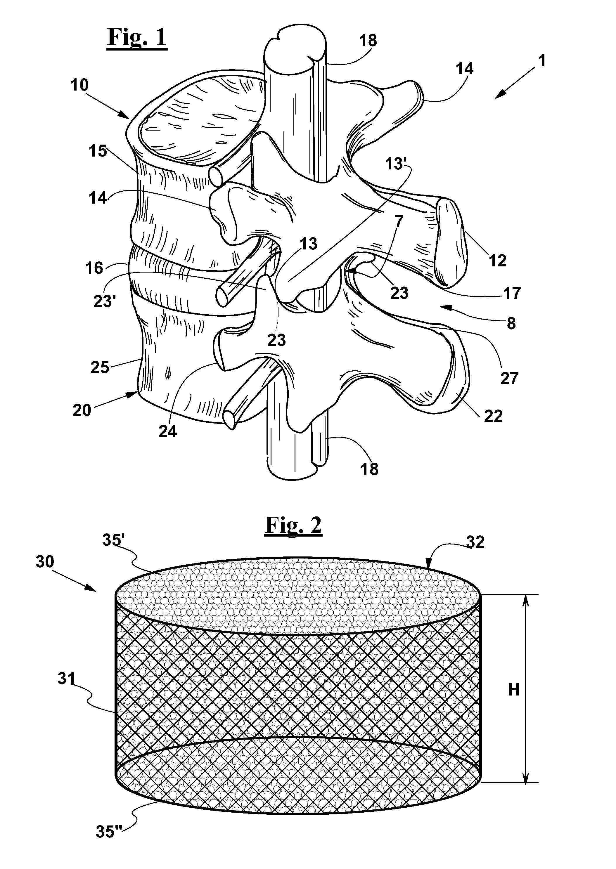
[0083]The involved anatomical parts are indicated in FIG. 1, which shows a subject's spinal segment 1 comprising two adjacent lumbar vertebrae 10 and 20. However, the device according to the invention can be used to form a vertebral fusion at any spinal level, provided that modifications are made that are obvious for a skilled person.

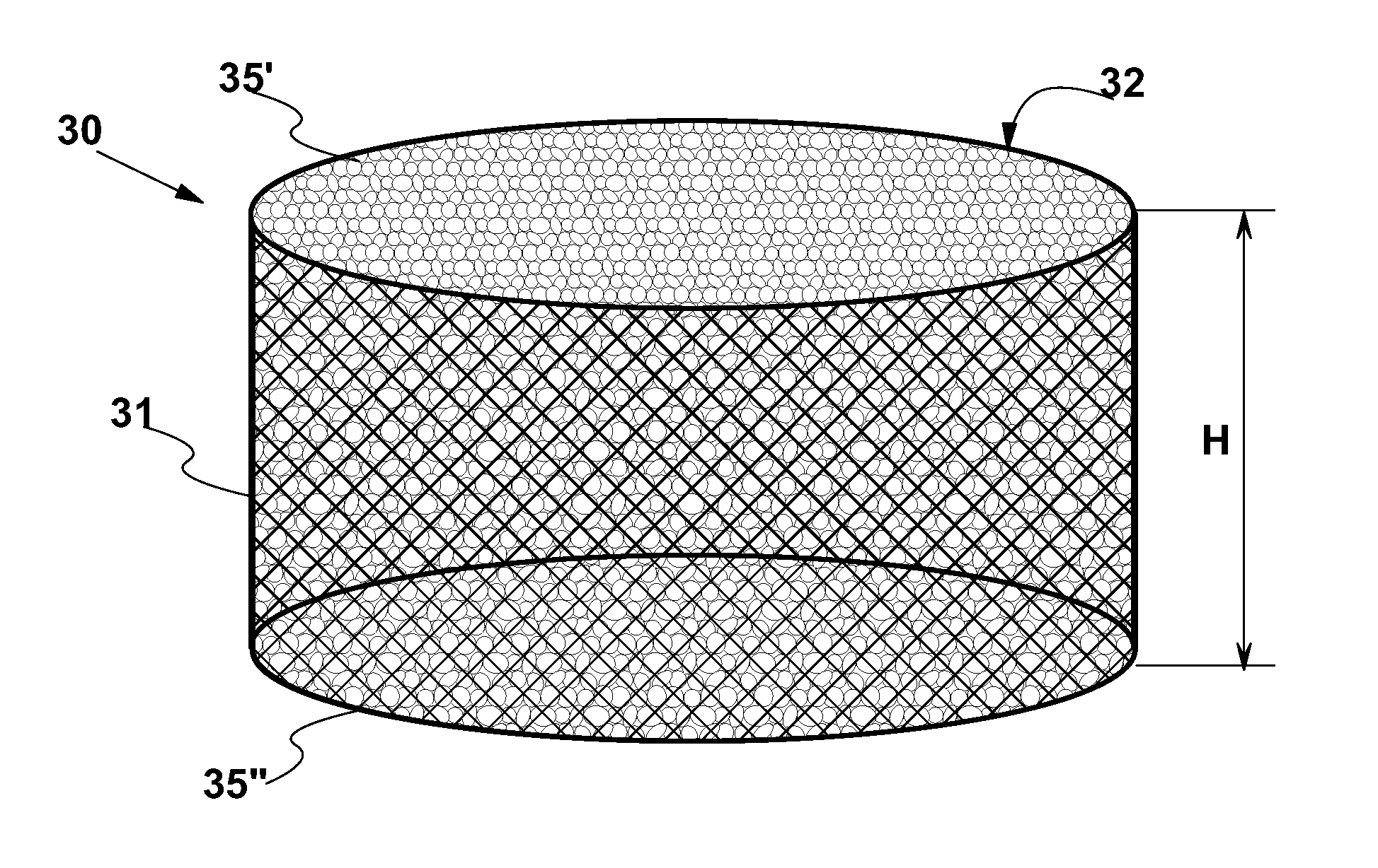
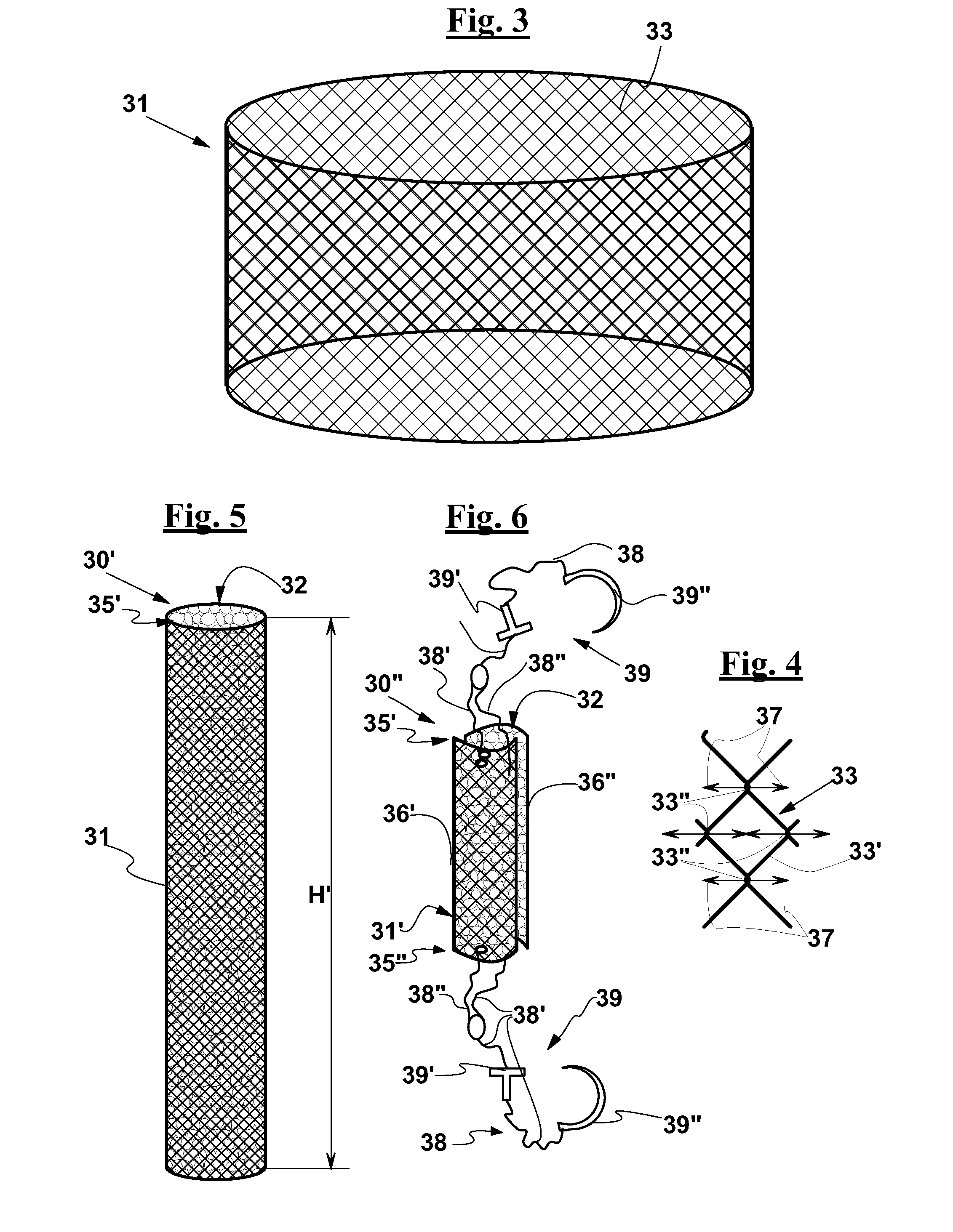
[0084]With reference to FIGS. 2, 3 and 4, a vertebral fusion device 30 is described that comprises a support element including a hollow container body and a predetermined amount of a plastically deformable granular osteosynthesis material 32 arranged in hollow container body 31.

[0085]In the exemplary embodiment of FIG. 1, device 30 has a substantially cylindrical shape, in particular a cylindrical shape with a circular cross section.

[0086]Device 30 may have a height H so as to be configured fo...


PUM


Abstract

A vertebral fusion device having a support element configured for insertion between two corresponding vertebral portions of two adjacent vertebrae, such as spinous processes and transverse processes, or joint surfaces of the vertebral bodies or of the facets, comprising a granular osteosynthesis material, preferably in cortico-spongeous chips made of bone bank human bone, which is plastically deformable, and a hollow container body that contains the osteosynthesis material and has a side wall, for example made with a network of interlaced meshes, and two open end portions to allow a contact between the osteosynthesis material and respective surfaces of said corresponding vertebral portions, so that the osteosynthesis material is kept in a compressed condition between said corresponding vertebral portions and receives mechanical loads therefrom which promote osteosynthesis.

Description

FIELD OF THE INVENTION[0001]The present invention relates to a device and to a vertebral fusion system, i.e. to a spinal fusion device and system. A procedure is also described for implanting said device, as well as a toolkit for carrying out this procedure.BACKGROUND OF THE INVENTION[0002]to Several devices are known for the fusion of adjacent vertebrae, among which:[0003]instrument-assisted fusion devices, comprising rods and screws for fixing the relative position of the vertebrae;[0004]“cage”-type fusion devices, which can be implanted by an anterior or is posterior or lateral approach;[0005]interspinous fusion devices, suitable for positioning between the spinous processes of two adjacent vertebrae.[0006]US2005 / 0055094 discloses a cage-type fusion device known as “Optimesh”. This device is suitable for insertion between two vertebral bodies to replace a damaged intervertebral disc, and comprises a closed cage element that is manufactured starting from a fibrous material. The ca...

Claims


Application Information

Patent Timeline
IPC IPC(8): A61F2/44
CPCA61F2/4455A61F2250/0067A61F2/442A61B17/025A61B17/7064A61B17/7065A61B17/707A61F2/30965A61F2/446A61B2017/0256A61F2310/00023A61F2002/30736
Inventor GUIZZARDI, GIANCARLOPETRINI, PIERO
Owner TSUNAMI
Why Eureka
Try Eureka