Detection of nano-scale particles with a self-referenced and self-heterodyned raman micro-laser

a nano-scale particle and micro-laser technology, applied in the field of nano-scale particle detection, can solve the problems of vibration, temperature rise, non-instantaneous response, etc., and achieve the effects of improving sensitivity and detection limit, small polarizabilities, and small polarization

Inactive Publication Date: 2015-10-08
WASHINGTON UNIV IN SAINT LOUIS
View PDF15 Cites 22 Cited by
  • Summary
  • Abstract
  • Description
  • Claims
  • Application Information

AI Technical Summary

Benefits of technology

[0023]The present technology as disclosed provides a dopant-free scheme, which retains the inherited biocompatibility of silica and can have widespread use for sensing in biological media. The Raman laser and operation band of the sensor can be tailored for the specific sensing environment and the properties of the targeted materials by changing the pump laser wavelength. This scheme also opens the possibility of using intrinsic Raman or parametric gain for loss compensation in other systems where dissipation hinders progress and limits applications.
[0026]The technology as disclosed demonstrates Raman gain-induced Q enhancement (linewidth narrowing via loss compensation), Raman gain-enhanced detection of mode splitting in the transmission spectra, and splitting in Raman lasing for single nanoparticle detection and counting. As demonstrated by test results, the technology as disclosed can detect NaCl nanoparticles of radii 10 nm that have smaller polarizabilities than polystyrene and gold nanoparticles of the same size. This level of sensitivity can be achieved without using plasmonic enhancement or any laser stabilization or noise cancelation schemes. However, integrating plasmonics and stabilization techniques into the technology scheme will further enable significant improvement in the sensitivity and detection limit.
[0028]The technology further realizes a higher sensitivity and a lower detection limit at single-particle resolution using WGMRs pumped below the lasing threshold (i.e., active resonators have much narrower linewidth and better sensitivity than a passive resonator) or above the lasing threshold (i.e., microlaser). The technology as disclosed also realizes a dopant-free low-threshold WGM micro-resonator / micro-laser for sensing applications, which retains the inherent biocompatibility of silica. The technology realizes faster detection due to the elimination of the need for scanning the wavelength of a tunable laser around a resonance to obtain the amount of splitting.
[0029]A WGM sensor with significantly lower cost can be achieved because the technology as disclosed eliminates the need for narrow linewidth tunable lasers and does not require dopants or plasmonic structures (i.e. in silica micro-toroids, Raman lasing with a fundamental linewidth as narrow as 4 Hz has been reported, which is reported to be much narrower than the commercially available tunable lasers). The technology also realizes the ability to use the same WGMR as a micro-laser with emission in different spectral bands just by changing the wavelength of the pump laser or by using a broadband pump.
[0030]In WGM micro-lasers with rare-earth-ion dopants, one should not only change the dopant but also the pump to obtain emission in different spectral windows. However, the present technology exploits the Raman gain, which enables one to operate the same WGMR at different wavelengths and loosens the requirement of a specific wavelength for pump lasers. The technology also introduces a method, which can be used to estimate the size of particles-this method can assign an average size to an ensemble of particles. WGM sensors can benefit from this in various ways, as demonstrated by the test data provided herein.
[0033]Raman lasing has been observed in silicon waveguide cavities, silicon waveguides within fiber ring cavities, silicon photonic crystal cavities, and WGMRs such as silicon micro-ring, silica microspheres, silica micro-toroids, glycerol-water droplets, and CaF2 disks. However, the technology as disclosed herein implements a different approach than previously seen by using Raman gain or Raman lasing for loss compensation to enhance optical detection capabilities at single-particle resolution.

Problems solved by technology

In particular, a non-instantaneous response is caused by vibrations of the crystal (or glass) lattice.
In addition, lattice vibrations are excited, leading to a temperature rise.

Method used


Image

  • Detection of nano-scale particles with a self-referenced and self-heterodyned raman micro-laser
  • Detection of nano-scale particles with a self-referenced and self-heterodyned raman micro-laser
  • Detection of nano-scale particles with a self-referenced and self-heterodyned raman micro-laser

Examples


Embodiment Construction

[0048]According to the embodiment(s) of the present invention, various views are illustrated in FIG. 1-8 and like reference numerals are being used consistently throughout to refer to like and corresponding parts of the invention for all of the various views and figures of the drawing. Also, please note that the first digit(s) of the reference number for a given item or part of the invention should correspond to the Fig. number in which the item or part is first identified.

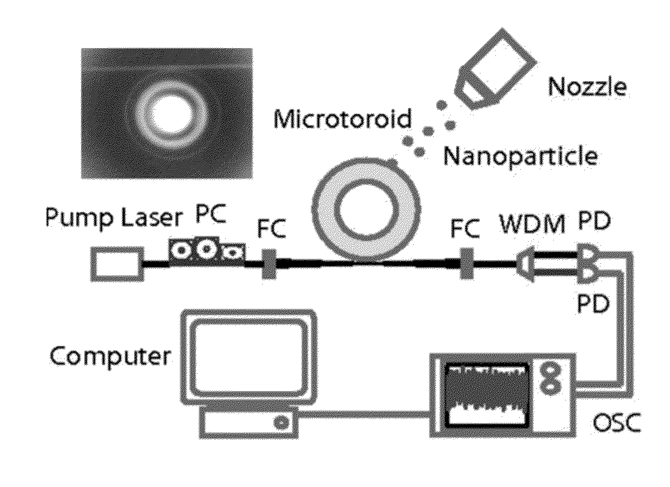
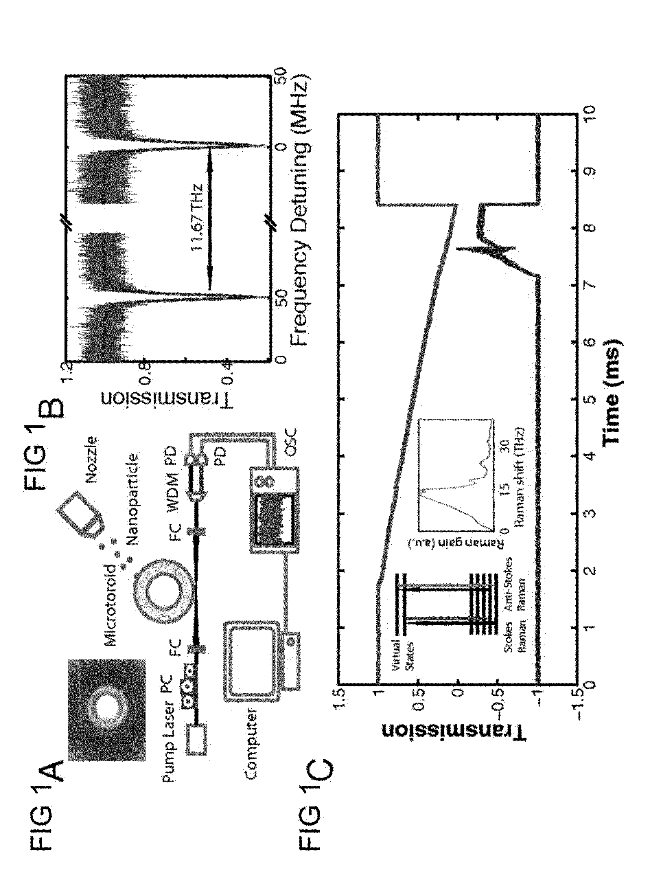
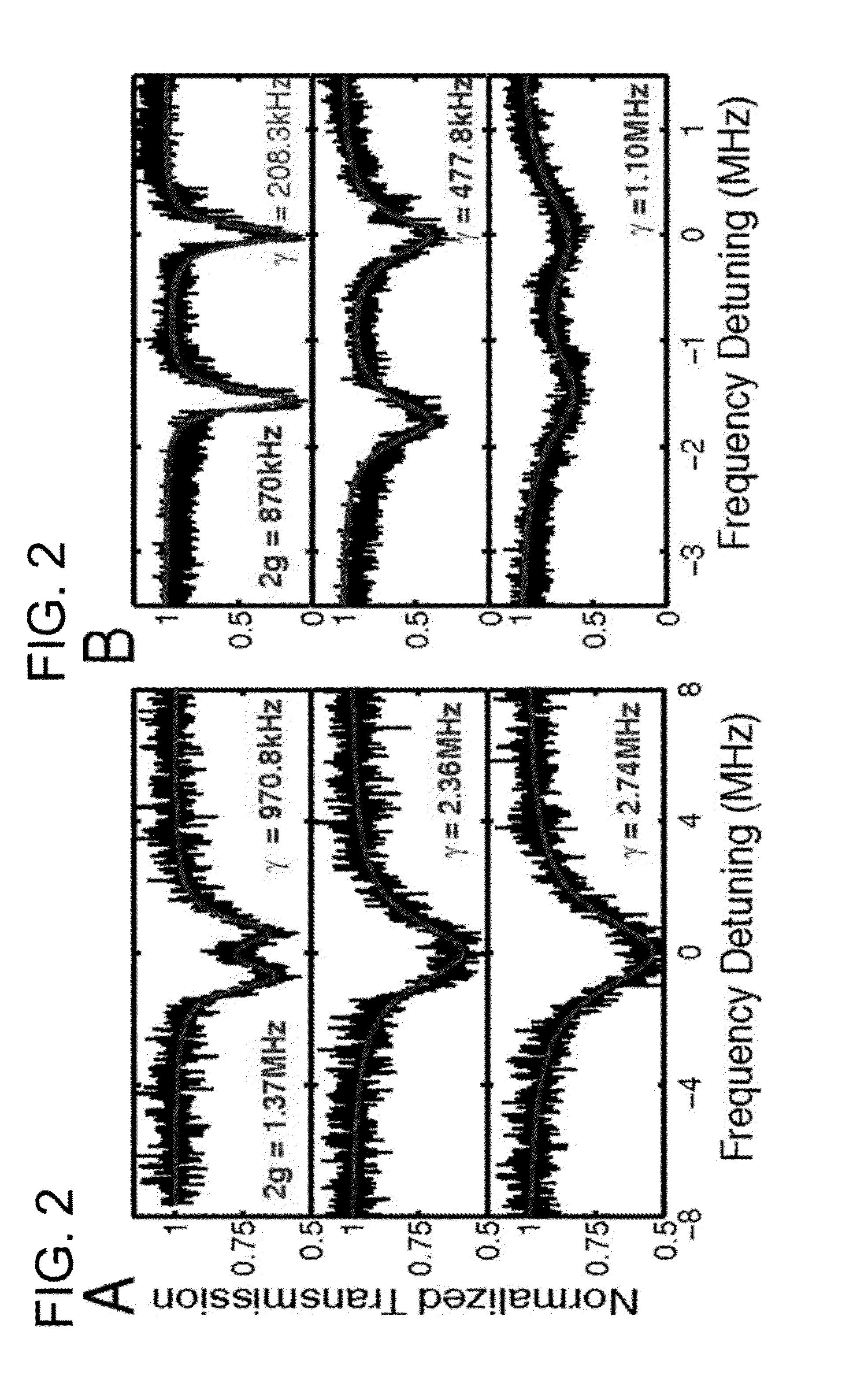
[0049]One embodiment of the present technology comprising whispering gallery mode resonator based nano-particle detection teaches a system and method for effectively detecting nano-sized particles. The details of the technology as disclosed and various implementations can be better understood by referring to the figures of the drawing. Referring to FIG. 1A, a diagram of one implementation of the photo-detection system is provided with a photodiode (PD) array monitor and optical spectral analyzer (OSC) setup is sho...


PUM

PropertyMeasurementUnit
diameteraaaaaaaaaa
diameteraaaaaaaaaa
frequencyaaaaaaaaaa

Abstract

A system and method for is a micro-laser based nano-scale object detection system and method using frequency shift and / or mode splitting techniques. The system and method can provide highly sensitive detection of nanoparticles with a self-referenced and self-heterodyned whispering-gallery Raman micro-laser. The system and method also provides for nano-particle size measurement.

Description

CROSS REFERENCE[0001]This Application Is A Continuation-In-Part Of And Claims The Benefit Of Application Ser. No. 13 / 460,170 Entitled SYSTEMS AND METHODS FOR PARTICLE DETECTION, Filed Apr. 30, 2012, Which Said Application Is Incorporated Herein By Reference In Its Entirety.U.S. GOVERNMENT RELATED CONTRACT(S) / GRANT(S)[0002]National Science Foundation under Grants 0954941 and 1264997;[0003]US Army Research Office under Grant W911NF-12-1-0026BACKGROUND[0004]1. Field[0005]This technology relates generally to nano-scale sized particle detection, and, more particularly, to detection of nano-scale sized particles using frequency shift and / or mode splitting techniques.[0006]2. Background Art[0007]With recent progress in nanotechnology, nanoparticles of different materials and sizes have been synthesized and engineered as key components in various applications ranging from solar cell technology to the detection of biomolecules. Meanwhile, nanoparticles generated by vehicles and industry have...

Claims


Application Information

Patent Timeline
Patent Type & Authority Applications(United States)
IPC IPC(8): G01N15/14G01N21/65
CPCG01N15/1434G01N2201/06113G01N21/65G01N21/7746Y10S977/88G01N2021/655
Inventor OZDEMIR, SAHIN KAYAYANG, LAN
Owner WASHINGTON UNIV IN SAINT LOUIS
Why Eureka
Try Eureka