

Image display device and light conversion panel used in same
a technology of image display and light conversion panel, which is applied in the direction of static indicating devices, lighting and heating apparatus, instruments, etc., can solve the problems of glare perception by the person seeing the image projected on the screen, and achieve the effect of widening the wavelength and phase range and reducing speckles
- Summary
- Abstract
- Description
- Claims
- Application Information
AI Technical Summary
Benefits of technology
Problems solved by technology
Method used
Image

Examples
embodiment 1
[0046]Hereinafter, an image display device and a light conversion panel used in the image display device according to Embodiment 1 will be described with reference to the drawings.
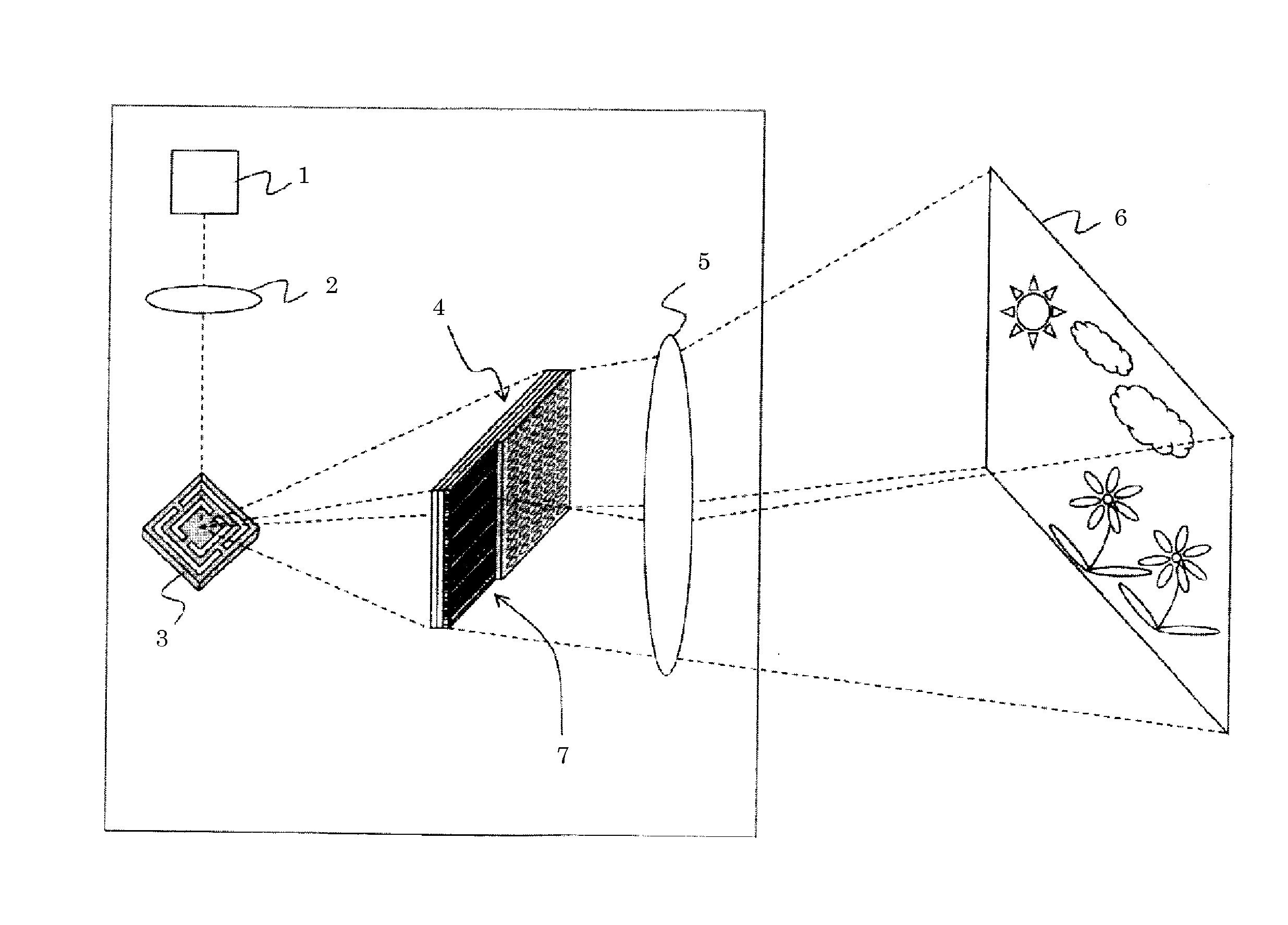
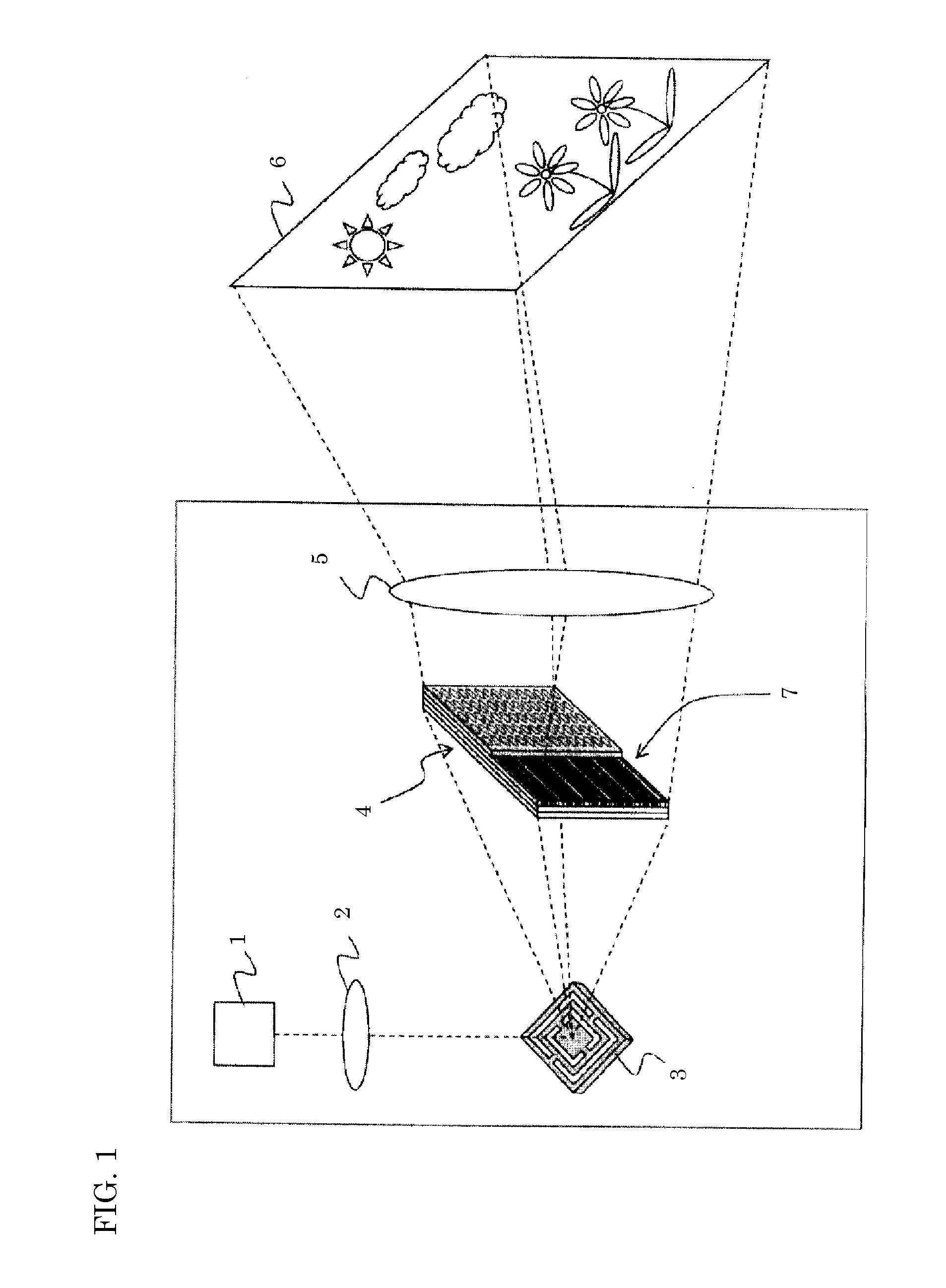
[0047]FIG. 1 is a schematic view illustrating a structure of the image display device according to Embodiment 1. The image display device according to Embodiment 1 includes laser source 1, collecting lens 2, deflecting element 3, light conversion panel 4, and projector lens 5. Laser source 1 emits excitation light (laser) which is near-ultraviolet light. Collecting lens 2 is disposed on the light-emission side of laser source 1 and collects the excitation light. Deflecting element 3 is disposed on the light-collection side of collecting lens 2 and scans the excitation light (i.e., scans the excitation light collected by collecting lens 2). Deflecting element 3 is a movable reflecting mirror, for example. Light conversion panel 4 converts the wavelength of the near-ultraviolet light (i.e., excitation light ...
embodiment 2
[0092]Hereinafter, an image display device according to Embodiment 2 will be described with reference to the drawings.
[0093]As illustrated in FIG. 13 and FIG. 14, the image display device according to Embodiment 2 includes: laser source 21 which emits excitation light which is near-ultraviolet light; collecting lens 22 which collects the excitation light; deflecting element 23 that is a movable reflecting mirror which scans the excitation light collected by collecting lens 22; light conversion panel 24 which absorbs a part of all of the excitation light scanned by deflecting element 23, converts the wavelength of the absorbed excitation light, and emits the resultant as fluorescence; and projector lens 25 which projects light emitted from light conversion panel 24.
[0094]The light from projector lens 25 is projected on screen 26.
[0095]Here, light conversion panel 24 includes a plurality of phosphor layers 27 which are planarly disposed, absorb near-ultraviolet light, and emit fluores...
embodiment 3
[0129]Hereinafter, an image display device according to Embodiment 3 will be described with reference to the drawings.
[0130]As illustrated in FIG. 24, the image display device according to Embodiment 3 includes first two-dimensional image generation unit 3080A, second two-dimensional image generation unit 3080B, and third two-dimensional image generation unit 3080C for red, green, and blue, respectively. Each of first two-dimensional image generation unit 3080A, second two-dimensional image generation unit 3080B, and third two-dimensional image generation unit 3080C includes laser source 3001 which emits excitation light which is near-ultraviolet light; collecting lens 3002 which collects the excitation light; deflecting element 3003 which is a movable reflecting mirror that scans the excitation light collected by collecting lens 3002; a light conversion panel which absorbs a part of all of the excitation light scanned by deflecting element 3003, converts the wavelength of the absor...
PUM
 Abstract
Description
Claims
Application Information