Voltage adjustment device for power distribution system, voltage adjusting method, and power control system
- Summary
- Abstract
- Description
- Claims
- Application Information
AI Technical Summary
Benefits of technology
Problems solved by technology
Method used
Image

Examples
embodiment
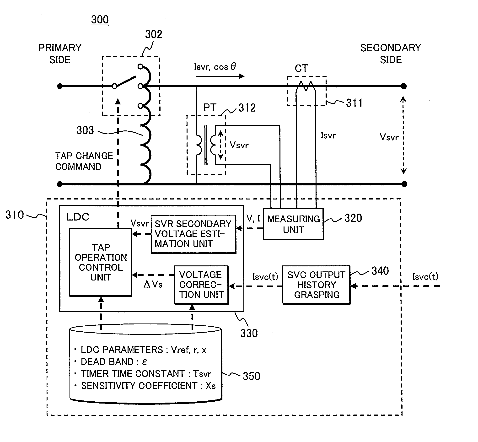
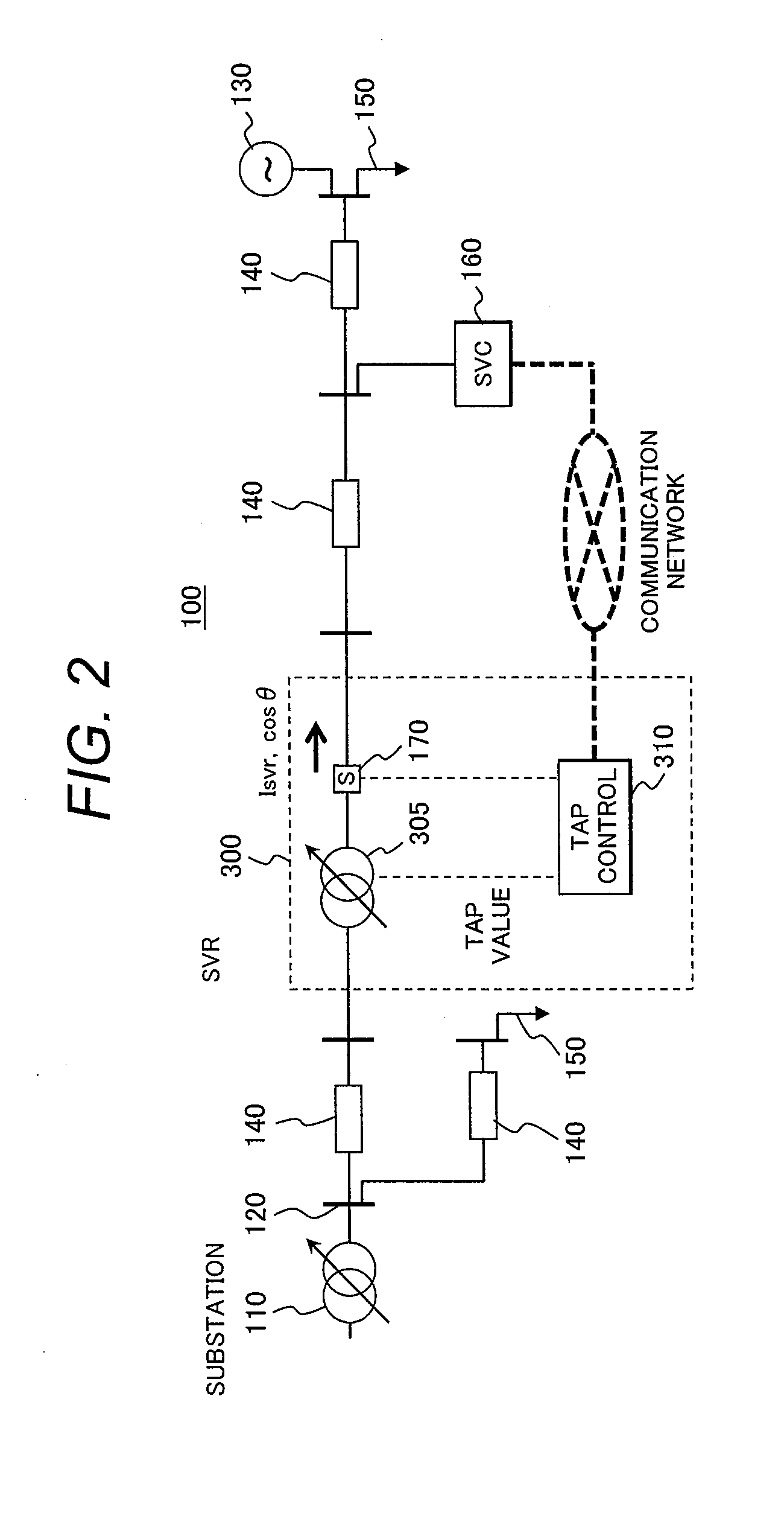
[0034]FIG. 2 illustrates an example of a distribution system 100 (feeder) including a voltage adjustment device 300 (on-load tap-changing transformer LRT or an automatic voltage regulator SVR) and a static var compensator 160 (SVC or STATCOM). In FIG. 2, an automatic voltage regulator SVR is installed as the voltage adjustment device 300. However, anon-load tap-changing transformer LRT may be installed as the voltage adjustment device 300.
[0035]The typical distribution system 100 shown in FIG. 2 includes nodes (buses) 120, a distribution line 140 connecting them, loads 150 and a solar power generation device 130 connected to the nodes 120, a sensor 170 installed in the distribution line, and a distribution substation 110.
[0036]The left side of FIG. 2 where the distribution substation 110 is located will be designated as the sending side of the feeder, and the right side will be designated as the end side of the feeder. The automatic voltage regulator 300 is a voltage adjustment devi...
PUM
 Abstract
Description
Claims
Application Information
 - Generate Ideas
- Intellectual Property
- Life Sciences
- Materials
- Tech Scout
- Unparalleled Data Quality
- Higher Quality Content
- 60% Fewer Hallucinations
Browse by: Latest US Patents, China's latest patents, Technical Efficacy Thesaurus, Application Domain, Technology Topic, Popular Technical Reports.
© 2025 PatSnap. All rights reserved.Legal|Privacy policy|Modern Slavery Act Transparency Statement|Sitemap|About US| Contact US: help@patsnap.com