Toroidal Plasma Channel with Varying Cross-Section Areas Along the Channel

a technology of toroidal plasma and channel, which is applied in the direction of nuclear reactors, greenhouse gas reduction, etc., can solve the problems of limited plasma device performance, undesirable or uncontrolled gas flow pattern and plasma profile, and plasma device not optimized in the entire plasma channel, so as to reduce the erosion of toroidal plasma channel, increase the dissociation rate of reactive gases, and prolong the effect of product li

Inactive Publication Date: 2015-10-08
MKS INSTR INC
View PDF4 Cites 0 Cited by
  • Summary
  • Abstract
  • Description
  • Claims
  • Application Information

AI Technical Summary

Benefits of technology

[0007]In one aspect, the invention features a toroidal plasma channel with varying cross-section areas along the channel to optimize gas flow and gas-plasma interactions. The plasma channel can also eliminate a sharp drop in dissociation rate at some particular flow rates, which occurred in previous toroidal plasma channel designs. In addition, plasma flow and gas-plasma interactions can be optimized by utilizing channel designs that are customized for a particular application or use. Further, this plasma channel design can reduce surface erosions by centering the plasma in the channel and controlling its profile, thereby extending the useful lifetime of the plasma chamber.
[0010]In yet another aspect, there is a kit for constructing a toroidal plasma chamber including an injection member capable of receiving and delivering a gas and an output member capable of allowing disassociated gas to flow out of the toroidal plasma chamber. A first side member and a second side member are capable of allowing gas and plasma to flow through a first inner cross-sectional area in at least a first portion and a second inner cross-sectional area in at least a second portion, respectively. The kit also includes a first inner cross-sectional area that is smaller than an inner cross-sectional area of a connecting portion of either the injection member or the output member, and a second inner cross-sectional area that is smaller than an inner cross-sectional area of a connecting portion of either the injection member or the output member. Water cooled connectors create a vacuum seal to prevent leakage of gas and plasma, and an electric break.
[0013]Each aspect described above can include one or more of the following features. In embodiments, the first and second side members come in various shapes and configurations to enhance performance of the assembly, kits, or methods. For example, in an embodiment, the first inner cross-sectional area (e.g., a section of the first side member) and the third inner cross-sectional area (e.g., a section of the second side member) can be the same. In various embodiments, the first side member and the second side member have a complementary shape. In some embodiments, the first side member and the second side member can be parallel. In embodiments, an inner cross-sectional area along the first side member and an inner cross-sectional area along the second side member can be connected in a smooth contour for continuous fluid flow.
[0015]In various embodiments, the first and second side members are removable. Both the first side member and the second side member can be connected to the injection member and the output member with connectors that create a vacuum seal to prevent leakage of gas and plasma and an electric break. In some embodiments, the connectors can be fluid cooled. The first side member and the second side member can be removable. The size of the first and the second side members can substantially match the size of plasma that is flowing through the toroidal plasma chamber.
[0016]The above aspects of invention have numerous advantages over the conventional state. For example, the invention can control gas flow and plasma profile. The invention can also increase dissociation rate of reactive gases and reduce toroidal plasma channel erosion. This can possibly extend product life while increasing power efficiency and improving plasma stability. The invention can also lower manufacturing costs and improve serviceability.

Problems solved by technology

However, performance of the plasma device remains limited by the chamber's design.
In existing toroidal plasma channel designs with a nearly uniform cross-section area, these changes in gas or plasma conditions create undesirable or uncontrolled gas flow patterns and plasma profiles.
As a result, the plasma device is not optimized in the entire plasma channel.
The erosion location in the plasma channel is also difficult to predict as it depends on the power, flow, pressure and species.
As a result, toroidal plasma devices have a limited lifetime.

Method used


Image

  • Toroidal Plasma Channel with Varying Cross-Section Areas Along the Channel
  • Toroidal Plasma Channel with Varying Cross-Section Areas Along the Channel
  • Toroidal Plasma Channel with Varying Cross-Section Areas Along the Channel

Examples


Embodiment Construction

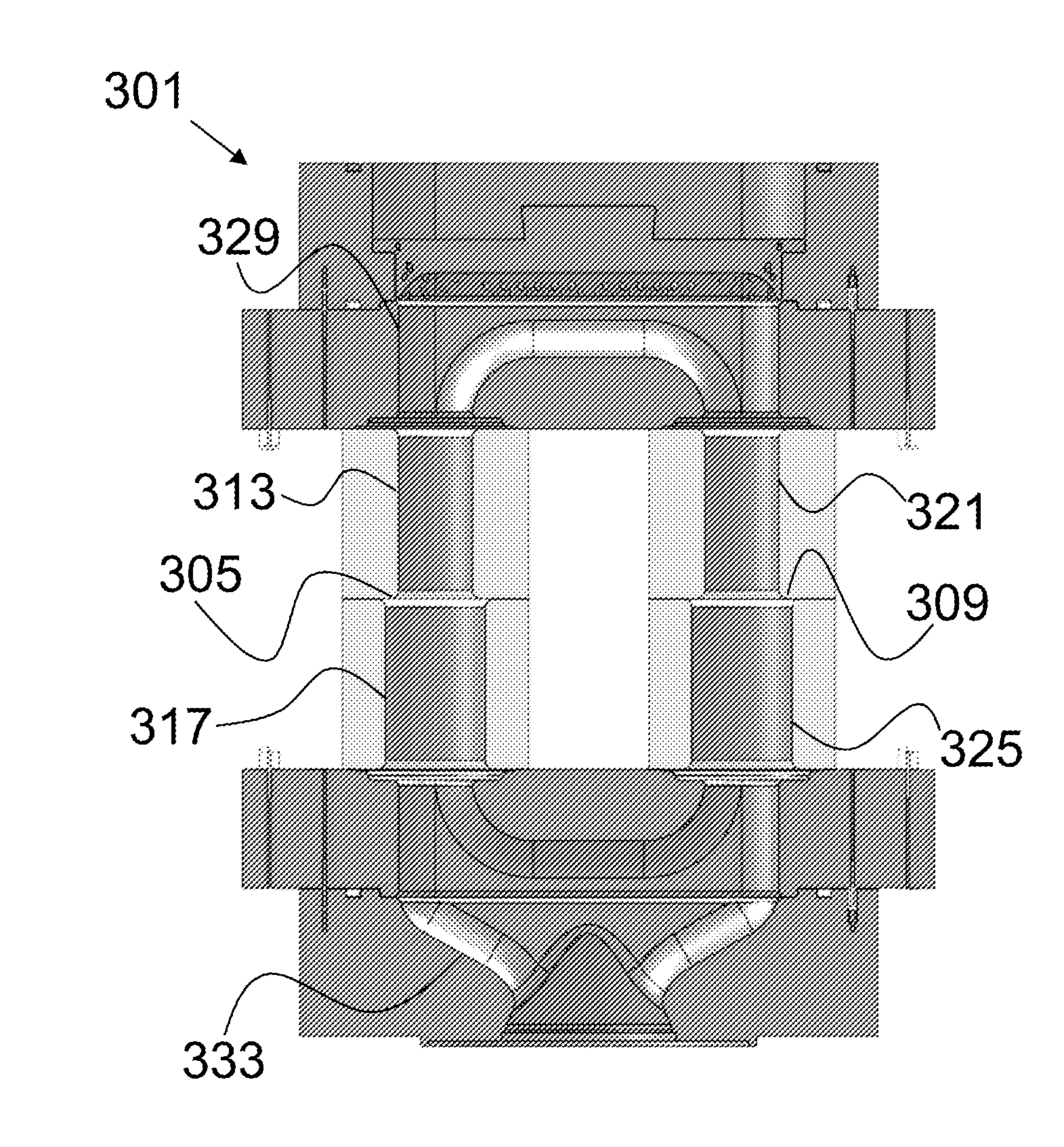
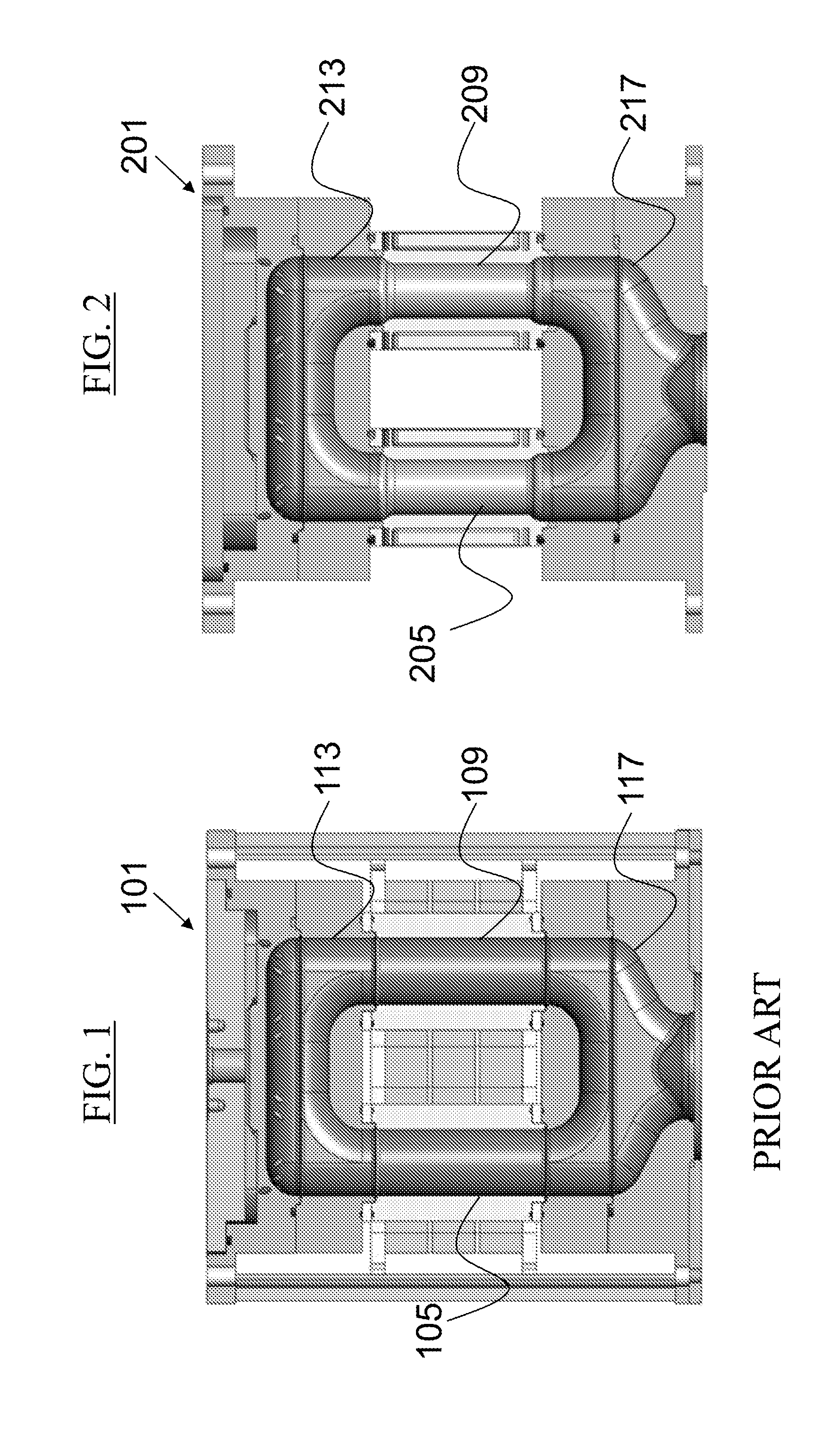
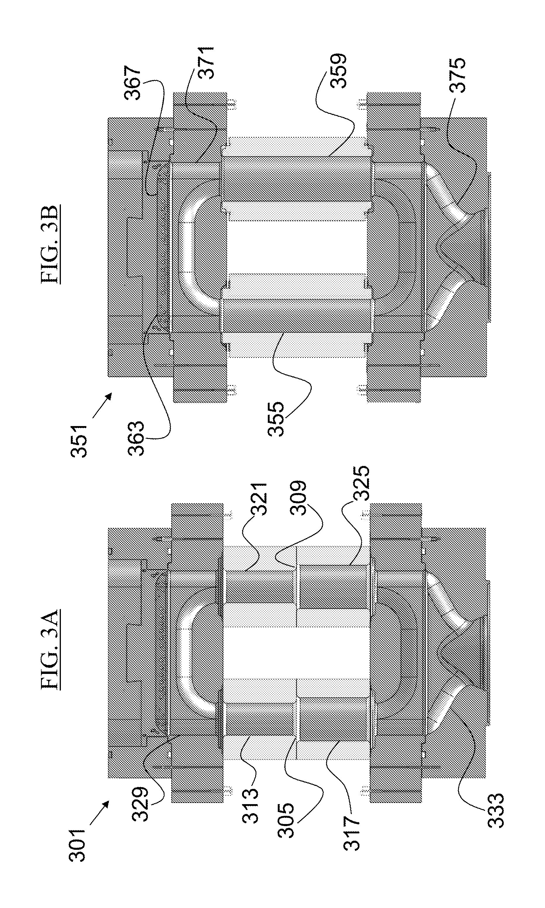
[0030]The present invention provides assemblies, kits, and methods for using toroidal plasma devices to adjust gas flow patterns and gas-plasma interactions. In general, toroidal plasma devices have a toroidal plasma chamber. p FIG. 1 shows a prior art embodiment of a toroidal plasma chamber 101. The toroidal plasma chamber 101 has a first side member 105 and a second side member 109. The toroidal plasma chamber 101 also has an injection member 113 and an output member 117. The injection member 113 is a point of entry where gas is introduced into the toroidal plasma chamber 101. The output member 117 is a point of exit where gas is permitted to exit the toroidal plasma chamber 101. A flow of gas will pass through both the first side member 105 and the second side member 109, encircling a channel inside the toroidal plasma chamber 101.

[0031]In existing toroidal plasma devices, the plasma channels have nearly-uniform cross-section areas. The first side member 105 has a substantially ...


PUM

PropertyMeasurementUnit
areaaaaaaaaaaa
areaaaaaaaaaaa
poweraaaaaaaaaa

Abstract

An assembly for adjusting gas flow patterns and gas-plasma interactions including a toroidal plasma chamber. The toroidal plasma chamber has an injection member, an output member, a first side member and a second side member that are all connected. The first side member has a first inner cross-sectional area in at least a portion of the first side member and a second inner cross-sectional area in at least another portion of the first side member, where the first inner cross-sectional area and the second inner-cross-sectional area being different. The second side member has a third inner cross-sectional area in at least a portion of the second side member and a fourth inner cross-sectional area in at least another portion of the second side member, where the third inner cross-sectional area and the fourth inner-cross-sectional area being different.

Description

CROSS REFERENCE TO RELATED APPLICATION[0001]This application is a divisional of U.S. patent application Se. No. 13 / 672,156 filed on Nov. 8, 2012 and claims the benefit of and priority to U.S. Provisional Patent Application No. 61 / 560,058, filed Nov. 15, 2011, both of which are owned by the assignee of the instant application and the entire disclosures of which are incorporated herein by reference.FIELD OF THE INVENTION[0002]This invention relates generally to toroidal plasma devices and more particularly to toroidal plasma devices with channels that can have varying sizes to adjust to different plasma sizes.BACKGROUND[0003]Plasma discharges can be used to excite gases to produce activated gases containing ions, free radicals, atoms and molecules. Activated gases are used for numerous industrial and scientific applications including processing solid materials such as semiconductor wafers, powders, and other gases. The parameters of the plasma and the conditions of the exposure of the...

Claims


Application Information

Patent Timeline
Patent Type & Authority Applications(United States)
IPC IPC(8): H01J37/32
CPCH01J37/32449H01J2237/006H01J37/32513H01J37/32009C23C16/45587C23C16/45591G21B1/17H01J37/321H01J37/32357H05H1/12H01J37/32807C23C16/50Y10T137/0318Y10T137/8376Y02E30/10F17D1/04
Inventor HU, CHAOLINCHEN, XING
Owner MKS INSTR INC
Why Eureka
Try Eureka