Apparatus and methods for regulating cryogenic treatment

a technology of cryogenic treatment and apparatus, applied in the field of medical devices, can solve the problems of radiofrequency ablation, frequent lack of visualization, incomplete ablation, etc., and achieve the effect of prolonging the available time and slowing the cooling rate of the reservoir or canister

Active Publication Date: 2015-10-15
CHANNEL MEDSYST
View PDF9 Cites 26 Cited by
  • Summary
  • Abstract
  • Description
  • Claims
  • Application Information

AI Technical Summary

Benefits of technology

[0034]With the heating element and temperature sensor so coupled to the microprocessor or controller, the heating assembly may form a closed-loop system where the microprocessor or controller may be programmed via a software algorithm to control the electrical power supplied to the heating element depending upon the measured temperature of the temperature sensor such that

Problems solved by technology

While successful in several arenas, radiofrequency ablation has several major downsides, including incomplete ablation, frequent lack of visualization during catheter insertion, potential for overlap during treatment (with some areas receiving twice as muc

Method used


Image

  • Apparatus and methods for regulating cryogenic treatment
  • Apparatus and methods for regulating cryogenic treatment
  • Apparatus and methods for regulating cryogenic treatment

Examples


Embodiment Construction

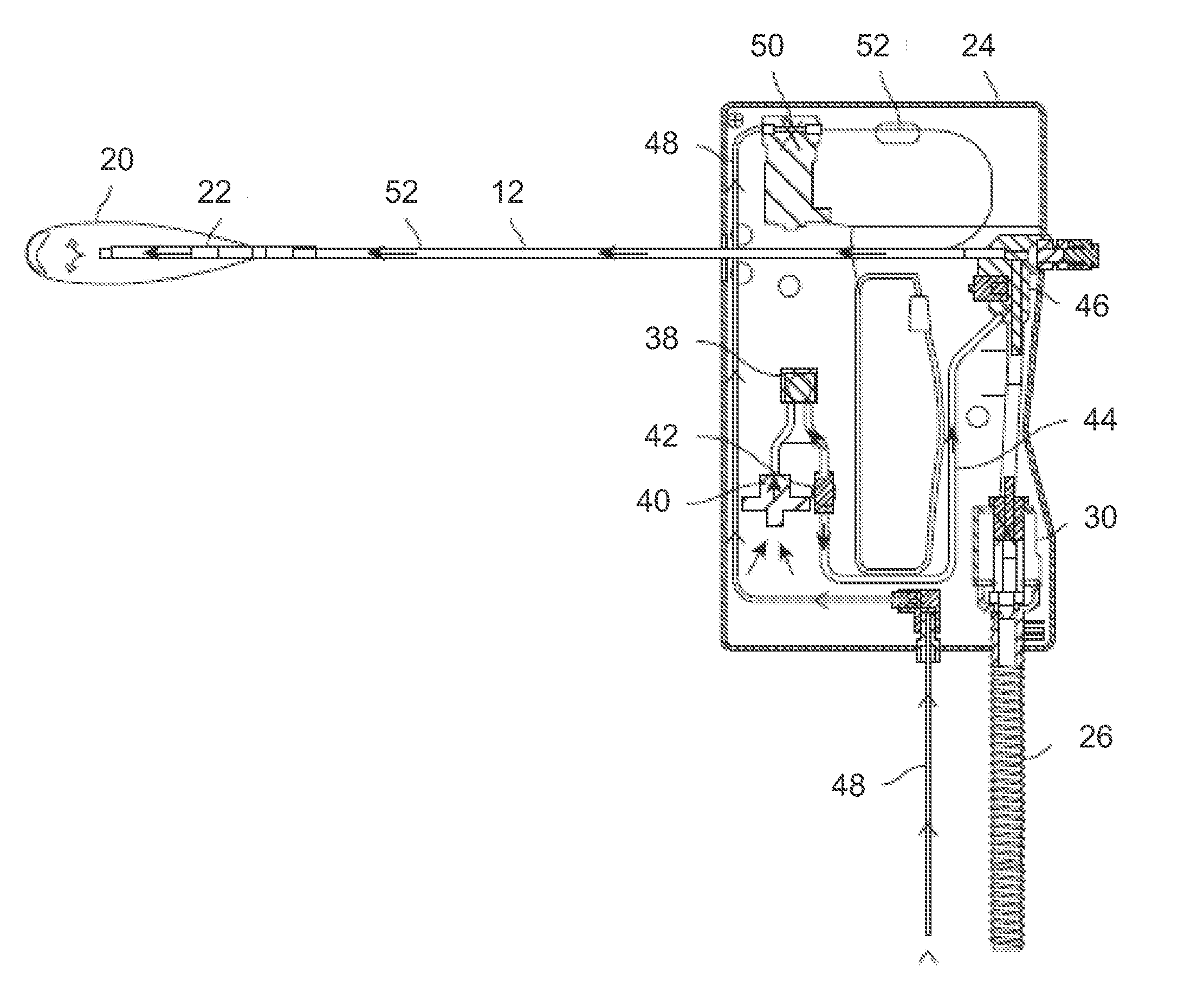
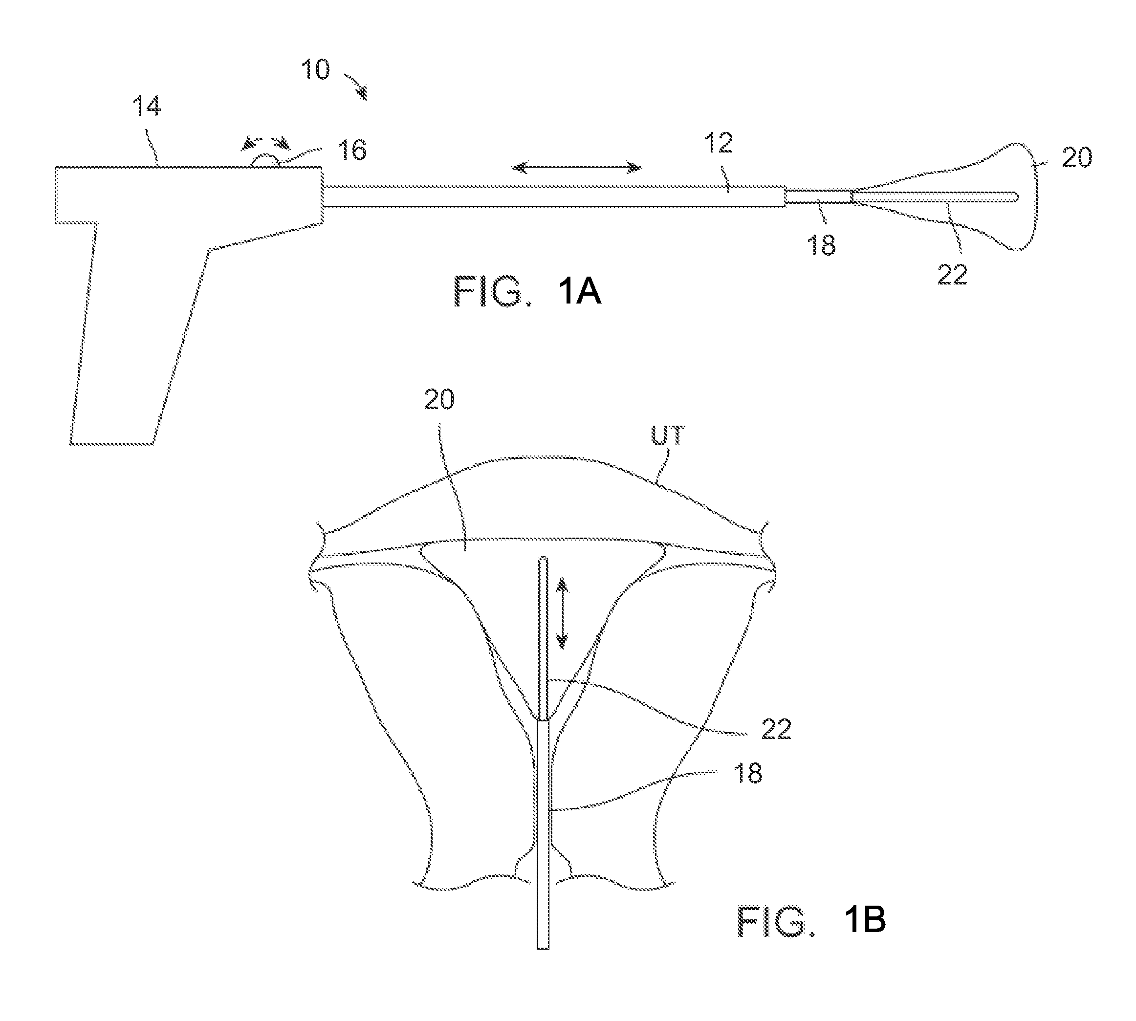
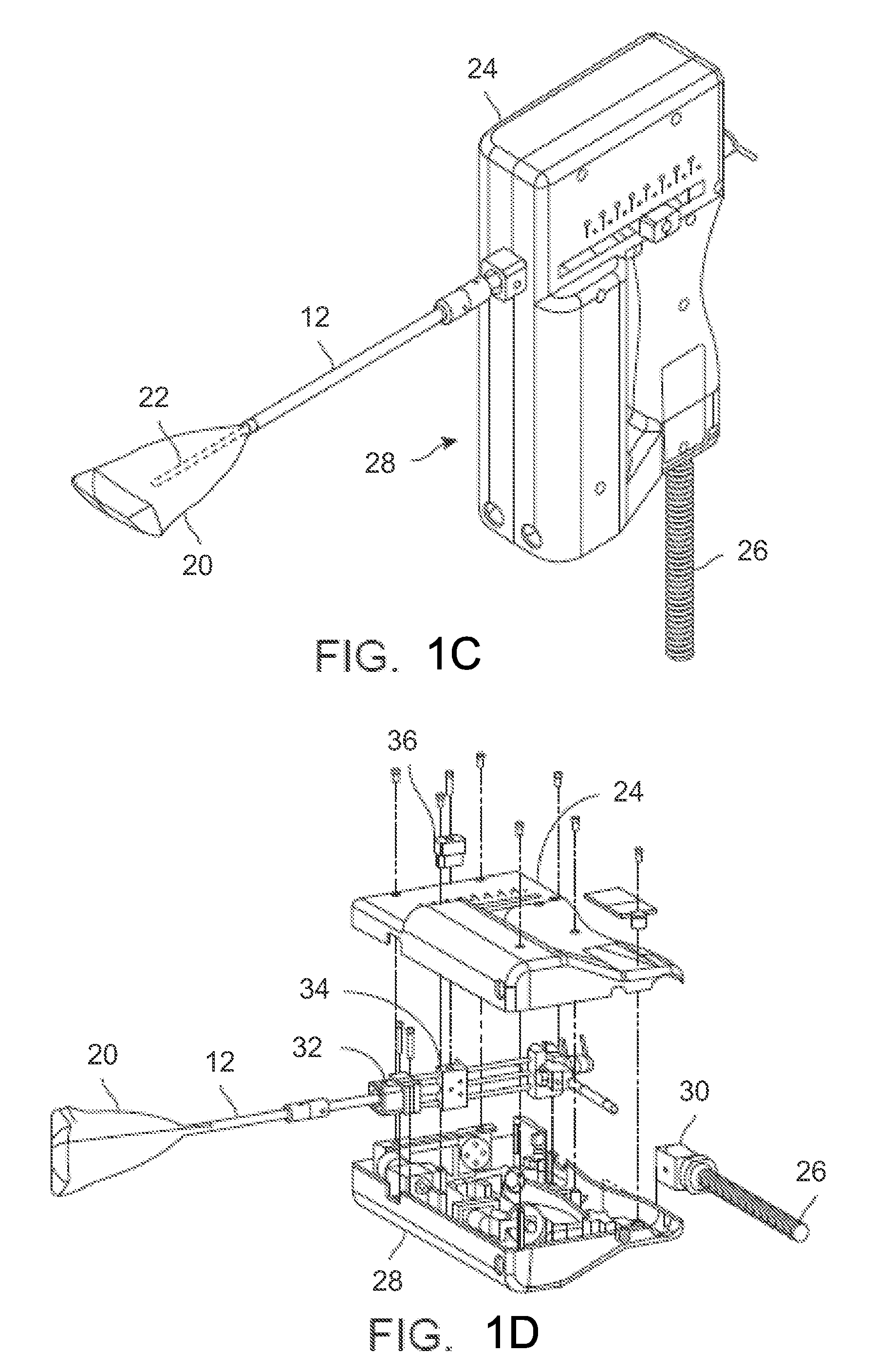
[0065]The cooling probe 22 as well as the balloon assembly may be variously configured, for instance, in an integrated treatment assembly 10 as shown in the side view of FIG. 1A. In this variation, the assembly 10 may integrate the elongate shaft 18 having the liner or balloon 20 extending therefrom with the cooling probe 22 positioned translatably within the shaft 18 and liner 20. A separate translatable sheath 12 may be positioned over the elongate shaft 18 and both the elongate shaft 18 and sheath 12 may be attached to a handle assembly 14. The handle assembly 14 may further comprise an actuator 16 for controlling a translation of the sheath 12 for liner 20 delivery and deployment.

[0066]With the sheath 12 positioned over the elongate shaft 18 and liner 20, the assembly 10 may be advanced through the cervix and into the uterus UT where the sheath 12 may be retracted via the handle assembly 14 to deploy the liner 20, as shown in FIG. 1B. As described above, once the liner 20 is ini...


PUM


Abstract

Apparatus and methods for regulating cryogenic treatments are disclosed which comprise devices and methods for delivering controlled treatment of a cryoablative agent. In one variation, such devices may generally comprise an elongate probe having a distal tip and a flexible length, at least one infusion lumen positioned through or along the elongate probe, wherein the infusion lumen defines one or more openings along its length, and a liner expandably enclosing the probe. An inflow reservoir or canister valve may be fluidly coupled with a reservoir or canister containing the cryoablative agent and a modulation control unit may also be fluidly coupled with the inflow reservoir or canister valve and in fluid communication with the at least one infusion lumen. Additionally, a warming element may also be thermally coupled with the reservoir or canister.

Description

CROSS-REFERENCE TO RELATED APPLICATIONS[0001]This application claims the benefit of priority to U.S. Prov. App. 61 / 977,773 filed Apr. 10, 2014, which is incorporated herein by reference in its entirety.FIELD OF THE INVENTION[0002]The present invention relates to medical devices. In particular, the present invention relates to methods and apparatus for regulating the cryoablative treatment of tissue regions.BACKGROUND OF THE INVENTION[0003]In the last few decades, therapeutic intervention within a body cavity or lumen has developed rapidly with respect to delivery of energy via radiofrequency ablation. While successful in several arenas, radiofrequency ablation has several major downsides, including incomplete ablation, frequent lack of visualization during catheter insertion, potential for overlap during treatment (with some areas receiving twice as much energy as other areas), charring of tissues and requirements for frequent debridement, frequent requirements for additional doses ...

Claims


Application Information

Patent Timeline
IPC IPC(8): A61B18/02
CPCA61B2018/0268A61B18/0218A61B2018/00041A61B2018/0022A61B2018/00559A61B2018/00577A61B2018/00744A61B2018/00791A61B18/02
Inventor BURNETT, DANIEL R.COTE, RICMALECKI, WILLIAM W.NEIL, BRIAN M.BEAULIEU, DAVIDVOILES, BENJAMIN D.LOPRESTI, VINCENT
Owner CHANNEL MEDSYST
Why Eureka
Try Eureka