Antenna system using capacitively coupled compound loop antennas with antenna isolation provision

a compound loop antenna and antenna isolation technology, applied in the direction of loop antennas, simultaneous aerial operations, electrical equipment, etc., can solve the problems of deteriorating transmission and reception quality, affecting the effective implementation of such antennas, and being unsuitable for transmitters

Active Publication Date: 2015-10-15
DOCKON
View PDF4 Cites 23 Cited by
  • Summary
  • Abstract
  • Description
  • Claims
  • Application Information

AI Technical Summary

Problems solved by technology

However, effective implementation of such antennas is often confronted with size constraints due to a limited available space in the device.
As such, they are not typically suitable as transmitters.
However, in a configuration with multiple antennas, size constraints tend to become severe, and interference effects caused by electromagnetic coupling among the antennas may significantly deteriorate transmission and reception qualities.
At the same time, efficiency may deteriorate in many instances where multiple paths are energized and power consumption increases.

Method used


Image

  • Antenna system using capacitively coupled compound loop antennas with antenna isolation provision
  • Antenna system using capacitively coupled compound loop antennas with antenna isolation provision
  • Antenna system using capacitively coupled compound loop antennas with antenna isolation provision

Examples


Embodiment Construction

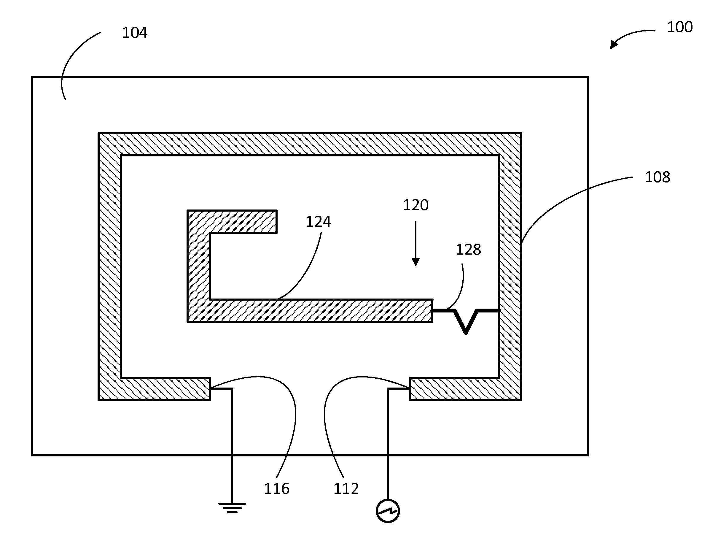
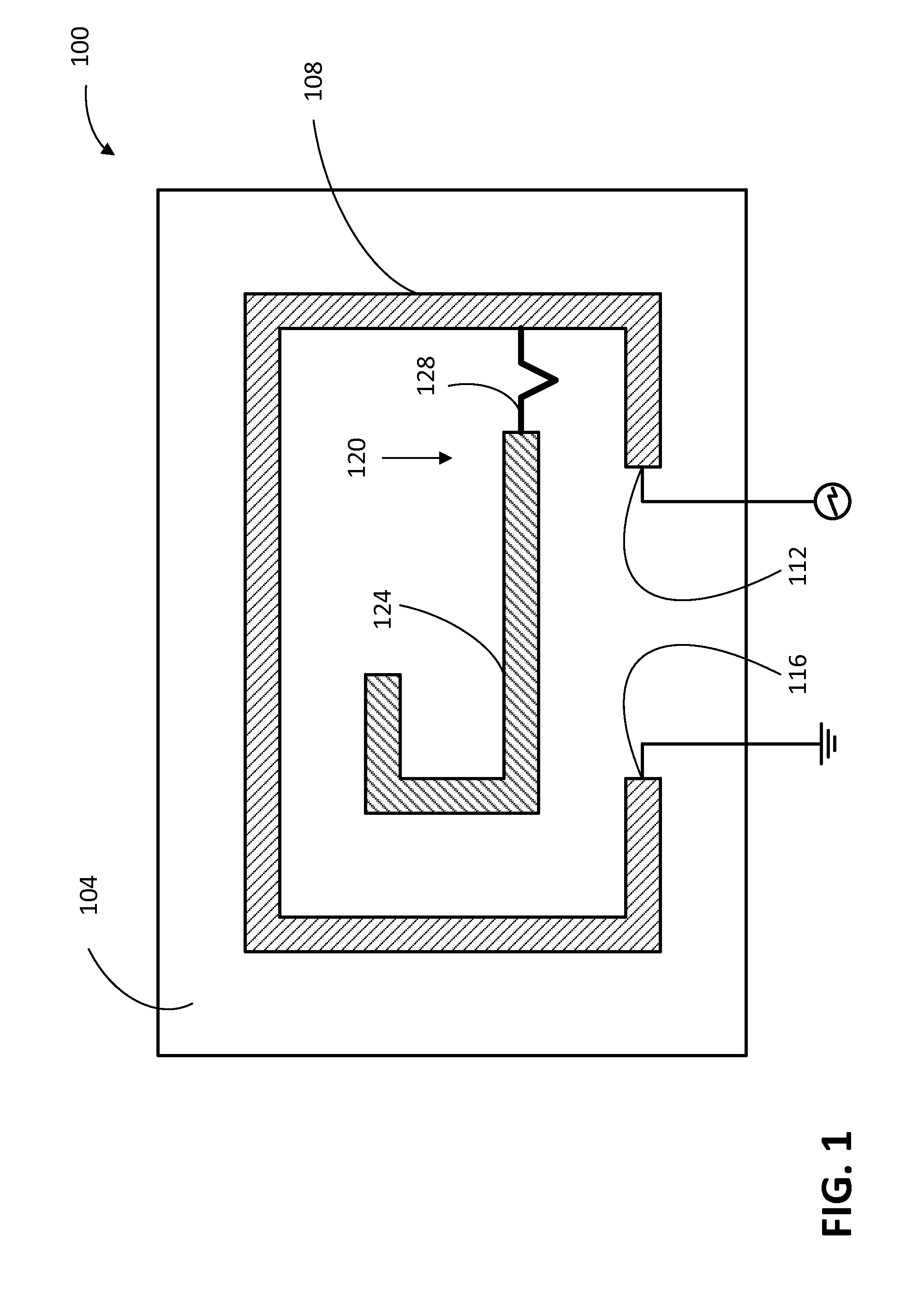
[0023]In view of known limitations associated with conventional antennas, in particular with regard to radiation efficiency, a compound loop antenna (CPL), also referred to as a modified loop antenna, has been devised to provide both transmit and receive modes with greater efficiency than a conventional antenna with a comparable size. Examples of structures and implementations of the CPL antennas are described in U.S. Pat. No. 8,144,065, issued on Mar. 27, 2012, U.S. Pat. No. 8,149,173, issued on Apr. 3, 2012, and U.S. Pat. No. 8,164,532, issued on Apr. 24, 2012. Key features of the CPL antennas are summarized below with reference to the example illustrated in FIG. 1.

[0024]FIG. 1 illustrates an example of a planar CPL antenna 100. In this example, the planar CPL antenna 100 is printed on a printed circuit board (PCB) 104, and includes a loop element 108, which in this case is formed as a trace along rectangle edges with an open base portion providing two end portions 112 and 116. On...


PUM


Abstract

An antenna system is provided, including a first antenna, a second antenna, a ground plane, and a resonant isolator coupled to the first and second antennas. Each of the antennas is configured to be a capacitively-coupled compound loop antenna, and the resonant isolator is configured to provide isolation between the two antennas at resonance. The two antennas may be symmetrical or asymmetrical and include a first element that emits a magnetic field and a second element that generates an electrical field that is orthogonal to the magnetic field. The radiating element of the second element may be capacitively coupled to the remainder of the second element. The resonate isolator may be comprised of a single conductive element or two conductive elements that are capacitively coupled.

Description

TECHNICAL FIELD[0001]The present disclosure relates to compound loop antenna.BACKGROUND[0002]As new generations of cellular phones and other wireless communication devices become smaller and embedded with increased applications, new antenna designs are required to address inherent limitations of these devices and to enable new capabilities. With conventional antenna structures, a certain physical volume is required to produce a resonant antenna structure at a particular frequency and with a particular bandwidth. However, effective implementation of such antennas is often confronted with size constraints due to a limited available space in the device.[0003]Antenna efficiency is one of the important parameters that determine the performance of the device. In particular, radiation efficiency is a metric describing how effectively the radiation occurs, and is expressed as the ratio of the radiated power to the input power of the antenna. A more efficient antenna will radiate a higher pr...

Claims


Application Information

Patent Timeline
Patent Type & Authority Applications(United States)
IPC IPC(8): H01Q5/307H01Q7/00H01Q21/30H01Q9/04
CPCH01Q5/307H01Q21/30H01Q7/00H01Q9/0407H01Q1/521H01Q5/371
Inventor BRINGUIER, JONATHAN NEILORSI, RYAN JAMESFOSTER, MATTHEW ROBERT
Owner DOCKON
Why Eureka
Try Eureka