
Thermal/acoustical liner

a technology of thermal acoustical liners and liners, which is applied in the direction of chemistry apparatus and processes, transportation and packaging, and synthetic resin layered products, etc., can solve the problems of increasing the weight of the aircraft, accelerating corrosion damage, and various performance issues of current thermal acoustical liners, etc., to achieve high strength, high performance, and high tear

Inactive Publication Date: 2015-10-22
COCOON INC
View PDF7 Cites 10 Cited by
  • Summary
  • Abstract
  • Description
  • Claims
  • Application Information

AI Technical Summary

Benefits of technology

The present invention is a multi-layer liner that includes a high-performance, fire-resistant insulation core layer made of a thermoplastic polyetherimide resin or equivalent, with two highly breathable layers on either side. The liner also has a facing layer that is fire-resistant and a backing layer that is also fire-resistant and highly breathable. The layers are adhesively connected to each other. This liner is able to provide superior insulation and protection against fire, while also allowing for breathability and flexibility.

Problems solved by technology

Current thermal acoustical liners, for example those used in aircraft, suffer from various performance issues.
The liners tend to trap moisture and contaminants, such as water, oil, sand, dust and pollutants against the air frame of the aircraft.
These liners are not breathable / air permeable and this leads to accelerated corrosion damage.
Additionally, the existing liners absorb moisture and hydrocarbon contaminants in the field, which adds significant additional weight to the aircraft when in use, as much as 50% or 81-94 lbs. per 100 sq. yards.
Additionally, the thermal and acoustical performance of current liners is limited due to limitations of fiberglass insulation and the quilting assembly that is required, compressing the insulation and degrading its thermal and acoustic properties.
Additionally, the fiberglass insulation fibers breakdown / degrade due to vibration (breakdown and compression of fiberglass) and absorption of moisture and oil / fuel contaminates.
As the liner becomes contaminated with dust, lubricants, fuel, hydraulic fluid, a fire hazard can be created.

Method used


Image

  • Thermal/acoustical liner
  • Thermal/acoustical liner

Examples


Embodiment Construction

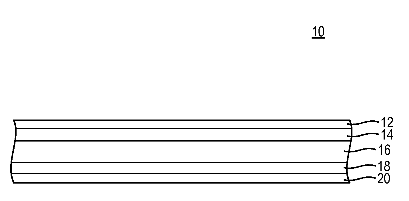
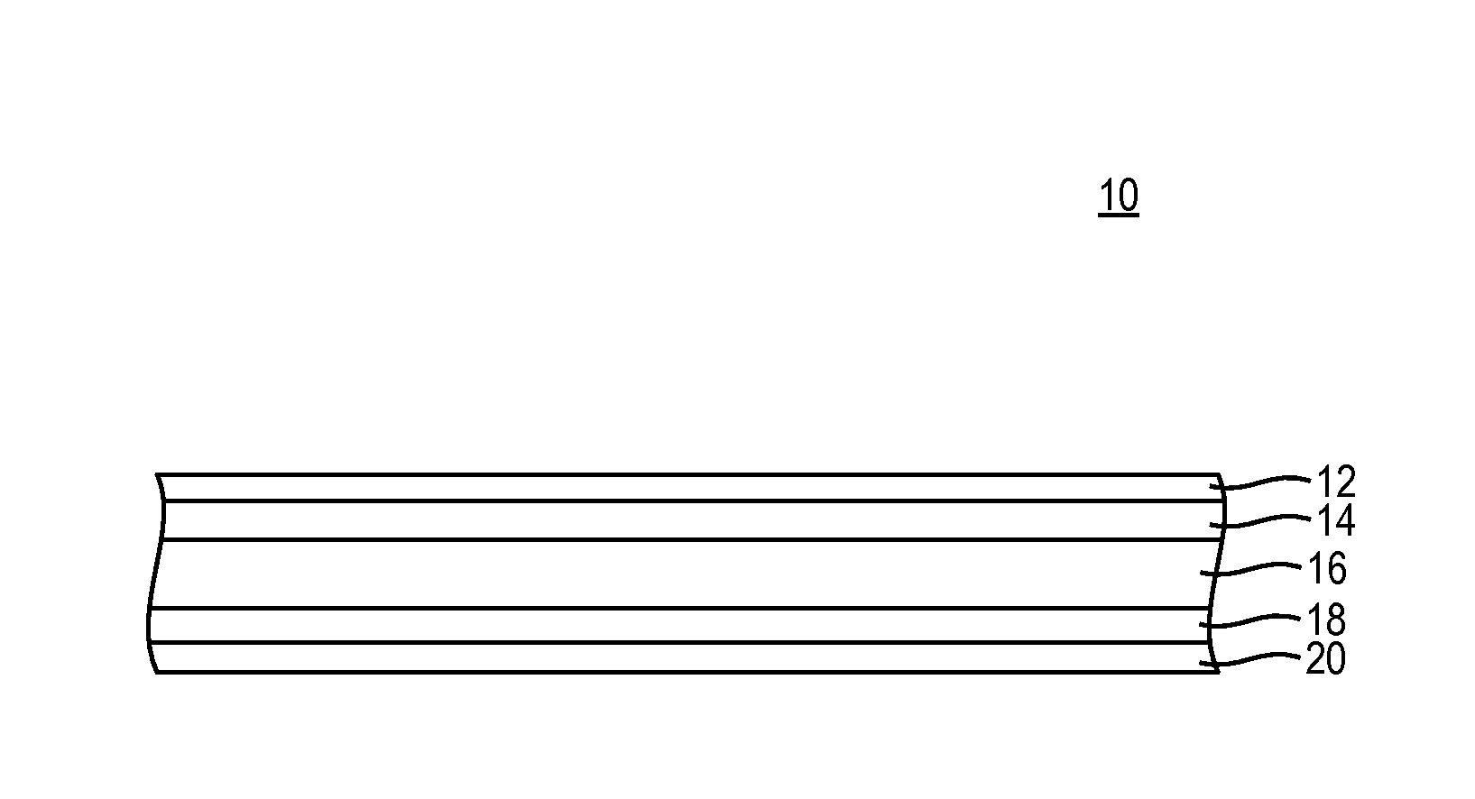
[0012]The present invention features a thermal acoustical liner 10, FIG. 1, which is breathable, hydrophobic, olio-phobic and fire-resistant. The liner is intended for use in a cargo aircraft on the interior airframe of the aircraft to help deaden acoustical noise coming from the airframe, although other uses are contemplated and within the scope of the present invention. The liner includes multiple layers, which are laminated to one another.

[0013]The acoustical liner 10 includes a facing layer 12 that is highly breathable and fire-resistant rated. The facing layer faces the interior (passenger and / or cargo) region of the aircraft. The facing layer must provide resistance to oil and water resistance with the overall 5 layer design having resistance to water entry pressures greater than 10 m of water and a surface oil resistance preventing the ingress of oils and other contaminants with surface tensions greater or above 21 dynes / cm. The facing 12 is preferably a high tenacity nylon 2...


PUM

PropertyMeasurementUnit
dry weightaaaaaaaaaa

Abstract

A multi-layer thermal acoustical liner is breathable, hydrophobic, oliophobic and fire-resistant rated. The liner includes a central insulation core layer contacted on a first surface by a first highly breathable layer and on a second surface by a second highly breathable layer. The first and second highly breathable layers are preferably an ePTFE membrane. The first highly breathable layer is adjacent a facing layer while the second highly breathable layer is adjacent a backing layer. The backing and facing layers are preferably nylon and treated with a fluorocarbon surface treatment for water repellency, UV resistance and mold / mildew resistance. At least one surface of one of the first or second highly breathable layers may include a carbon printing pattern to provide ESD protection. The layers of the liner are laminated to one another.

Description

CROSS-REFERENCE TO RELATED APPLICATIONS[0001]This application claims priority from U.S. Provisional Patent Application No. 61 / 767,443 entitled “Thermal / Acoustical Liner For Cargo Aircraft”, filed on Feb. 21, 2013 which is incorporated fully herein by reference.TECHNICAL FIELD[0002]The present invention relates to a thermal acoustical liner for use, for example, in aircraft and other similar environments.BACKGROUND INFORMATION[0003]Current thermal acoustical liners, for example those used in aircraft, suffer from various performance issues. The liners tend to trap moisture and contaminants, such as water, oil, sand, dust and pollutants against the air frame of the aircraft. These liners are not breathable / air permeable and this leads to accelerated corrosion damage.[0004]The liners currently used also add more weight to the aircraft than should be required in order to deliver the necessary sound deadening and thermal insulation performance requirements. For example, the build out of ...

Claims


Application Information

Patent Timeline
Patent Type & Authority Applications(United States)
IPC IPC(8): B32B27/32B32B27/12B32B5/02
CPCB32B27/322B32B5/022B32B5/02B32B27/12B32B2605/18B32B2307/102B32B2307/304B32B2307/21B32B2262/0269B32B27/14B32B2264/0257B64C1/40
Inventor CROTTY, MARKMCNAMARA, KATHERINE A.CROTTY, JR., LEO J.
Owner COCOON INC
Learn More