

Hydraulic Block for a Hydraulic Power Unit of a Hydraulic Vehicle Brake System
a technology of hydraulic power unit and hydraulic brake system, which is applied in the direction of braking system, machines/engines, engines without rotary main shafts, etc., can solve problems such as insufficient supply, and achieve the effect of eliminating the installation space of vacuum brake boosters
- Summary
- Abstract
- Description
- Claims
- Application Information
AI Technical Summary
Benefits of technology
Problems solved by technology
Method used
Image

Examples
Embodiment Construction
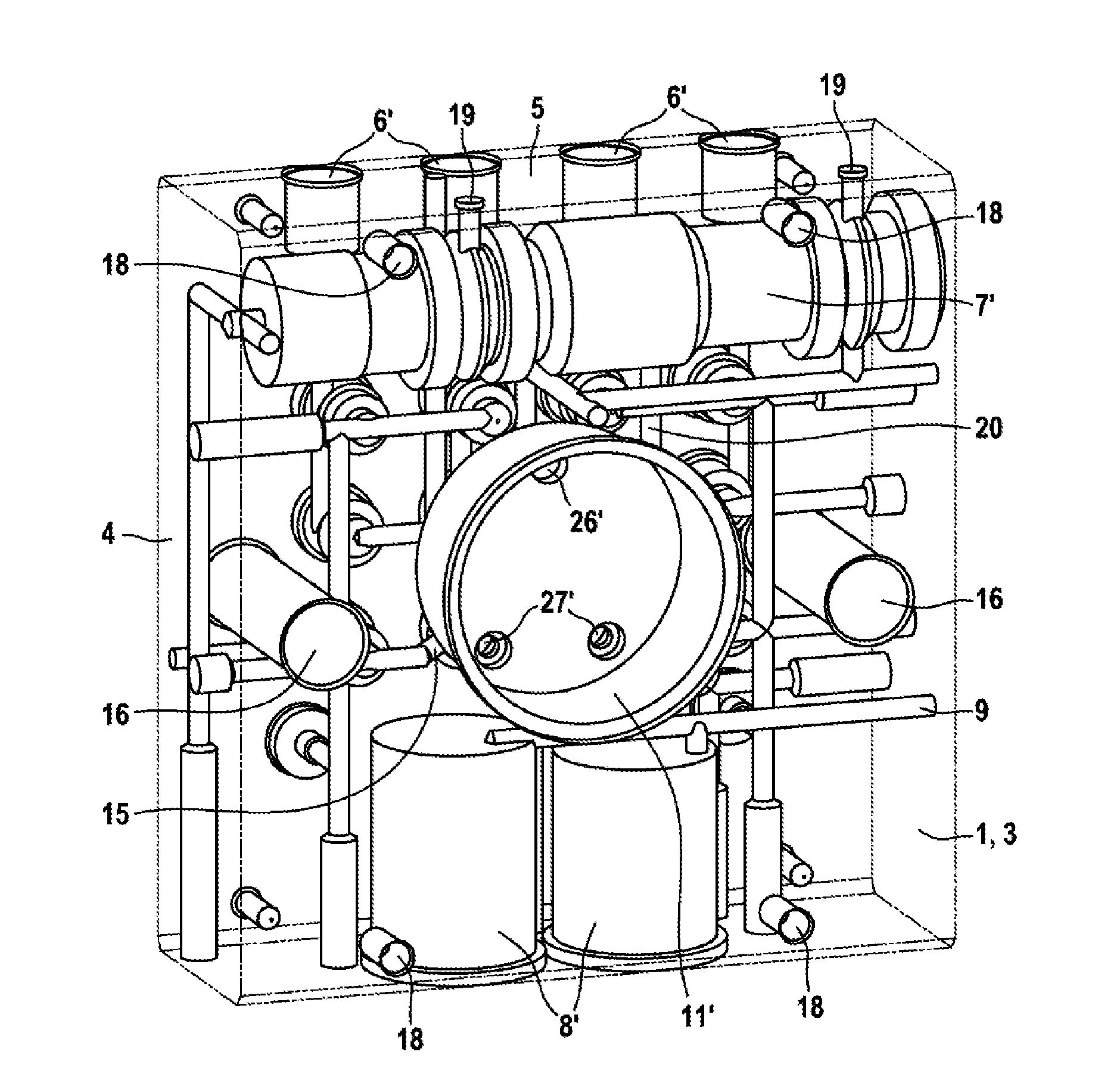
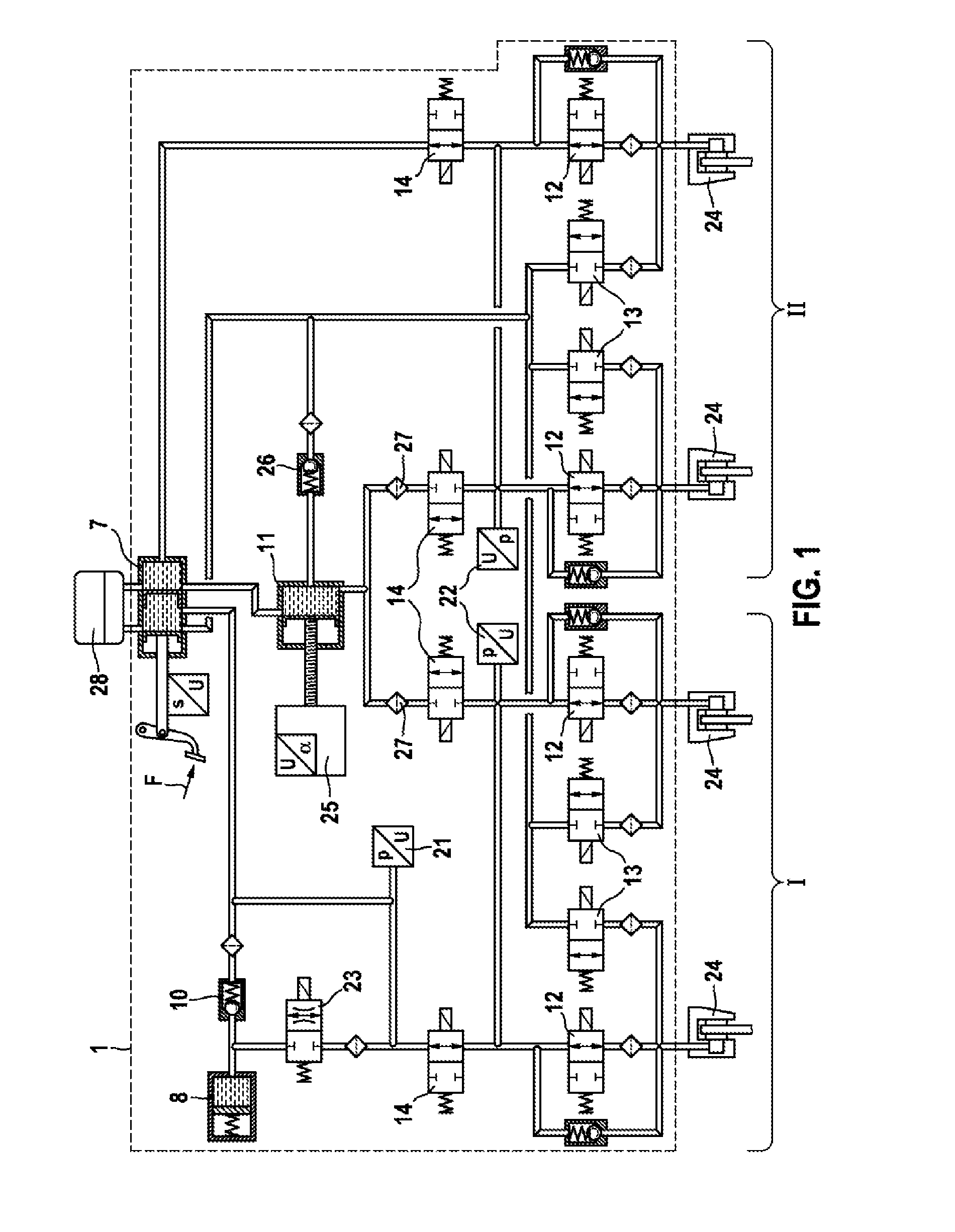
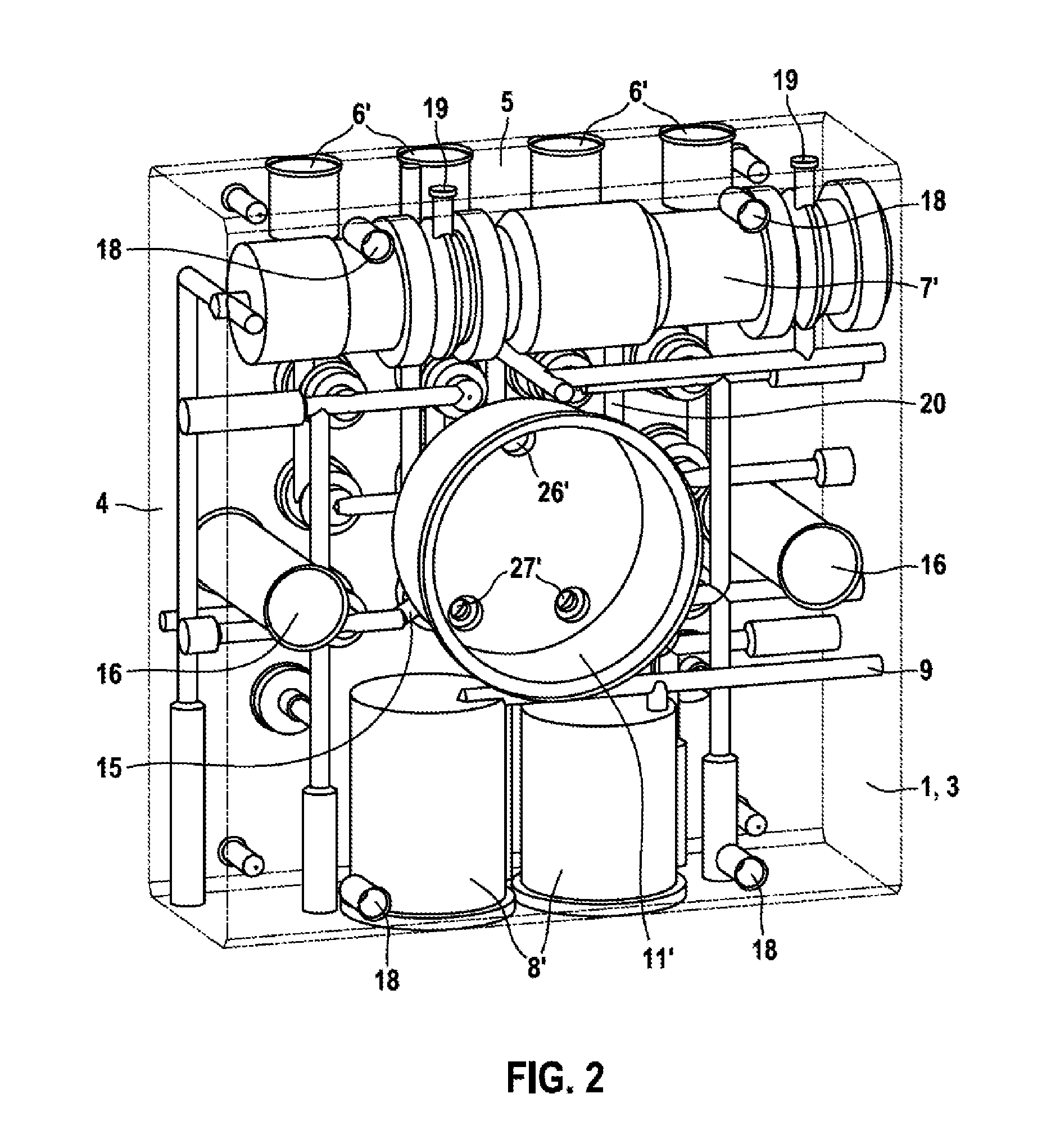
[0020]Hydraulic components of a hydraulic power unit of a slip control system in a vehicle brake system are accommodated in a hydraulic block 1, which is shown in FIGS. 2 and 3. A hydraulic circuit diagram of the vehicle brake system is depicted in FIG. 1. The vehicle brake system has a muscle-powered tandem or dual circuit brake master cylinder 7, to which two brake circuits I, II are connected. Each brake circuit I, II has two wheel brakes 24, which are each connected to the respective brake circuit I, II by a brake pressure buildup valve 12 and a brake pressure reduction valve 13. The brake pressure buildup valves 12 and brake pressure reduction valves 13 can also be understood as wheel brake pressure modulation valve arrangements, by means of which wheel brake pressures in the wheel brakes 24 and hence braking forces on the vehicle wheels can be regulated in a wheel-specific manner. Such control systems are known and will not be explained further here.
[0021]In each brake circuit...
PUM
 Abstract
Description
Claims
Application Information