
Method for operating a wind turbine

a technology of wind turbine and rotating shaft, which is applied in the direction of wind energy generation, machines/engines, waterborne vessels, etc., can solve the problems of reducing the required force to initiate motion in the respective sliding bearing standing still, and the static friction or so called stiction of the respective sliding bearings, so as to reduce the angle of wind attack, reduce the influence of wind energy on the rotational speed of the rotor hub, and reduce the angle of wind angl

Inactive Publication Date: 2015-10-22
SIEMENS AG
View PDF10 Cites 4 Cited by
  • Summary
  • Abstract
  • Description
  • Claims
  • Application Information

AI Technical Summary

Benefits of technology

The patent describes a wind turbine that can start and stop smoothly using a reversely operated generator as an electric motor. This prevents vibrations and oscillations from occurring during start-up or shut-down. The wind turbine also has a rotor blade pitch angle control means to adjust the angle of attack of wind on the rotor blades to increase or decrease the torque from the wind and support the rotor blades during start-up or shut-down. Additionally, the wind turbine may delay its start-up until the wind speed is above a certain threshold to improve its performance and reduce friction on its bearings.

Problems solved by technology

However, respective sliding bearings show comparatively high static friction or so called stiction, i.e. the required force to initiate motion in a respective sliding bearing standing still is comparatively high.
Yet, problems may arise in situations when wind energy is not enough and / or not even enough to force the rotor blades of a wind turbine to rotate, i.e. to force the respective sliding bearings in the desired state of hydrodynamic lubrication.
Even with supporting control of the blade pitch angles of the rotor blades, start-up of the wind turbine may be difficult in wind calm or uneven, gusty wind situations.

Method used


Image

  • Method for operating a wind turbine
  • Method for operating a wind turbine
  • Method for operating a wind turbine

Examples


Embodiment Construction

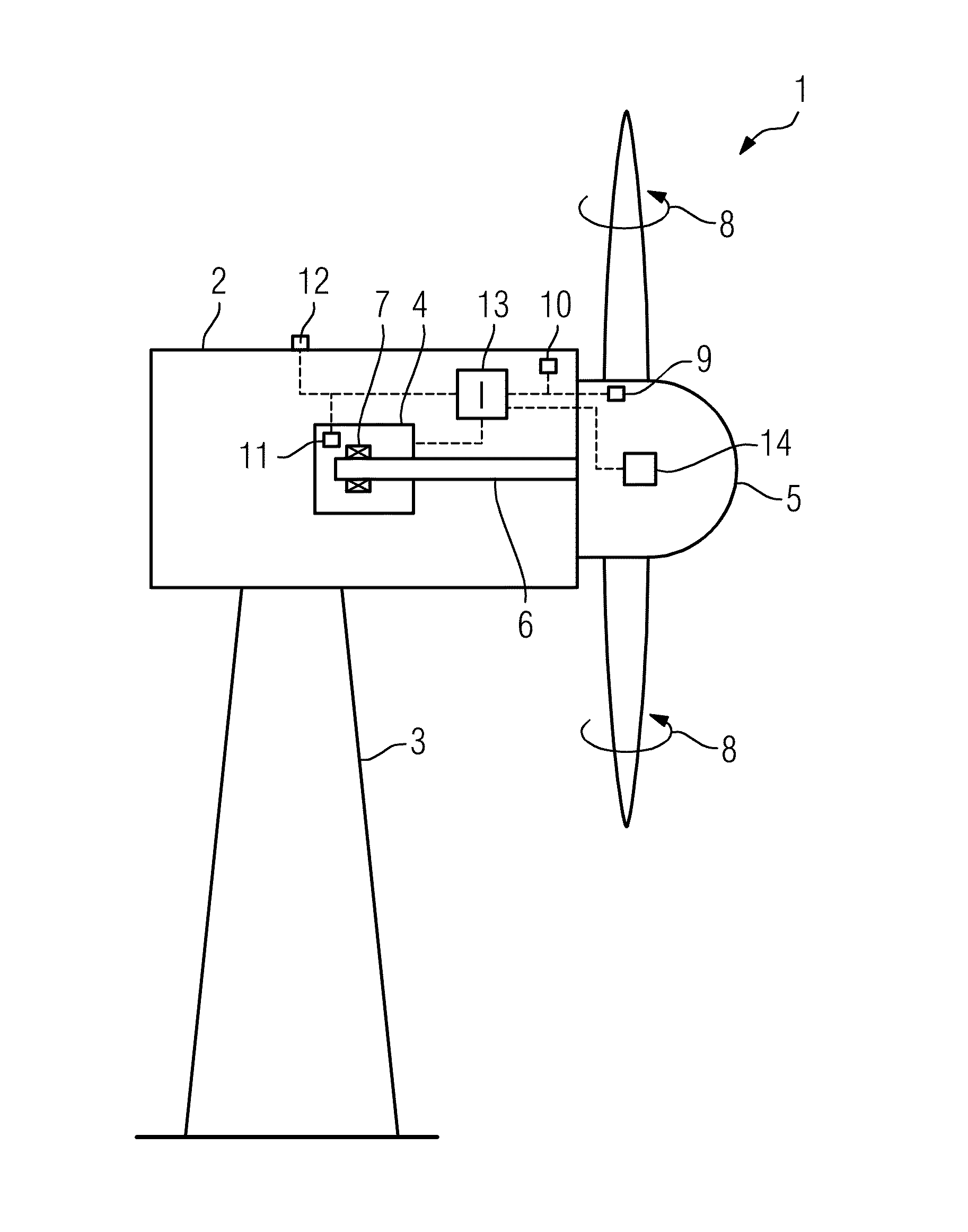
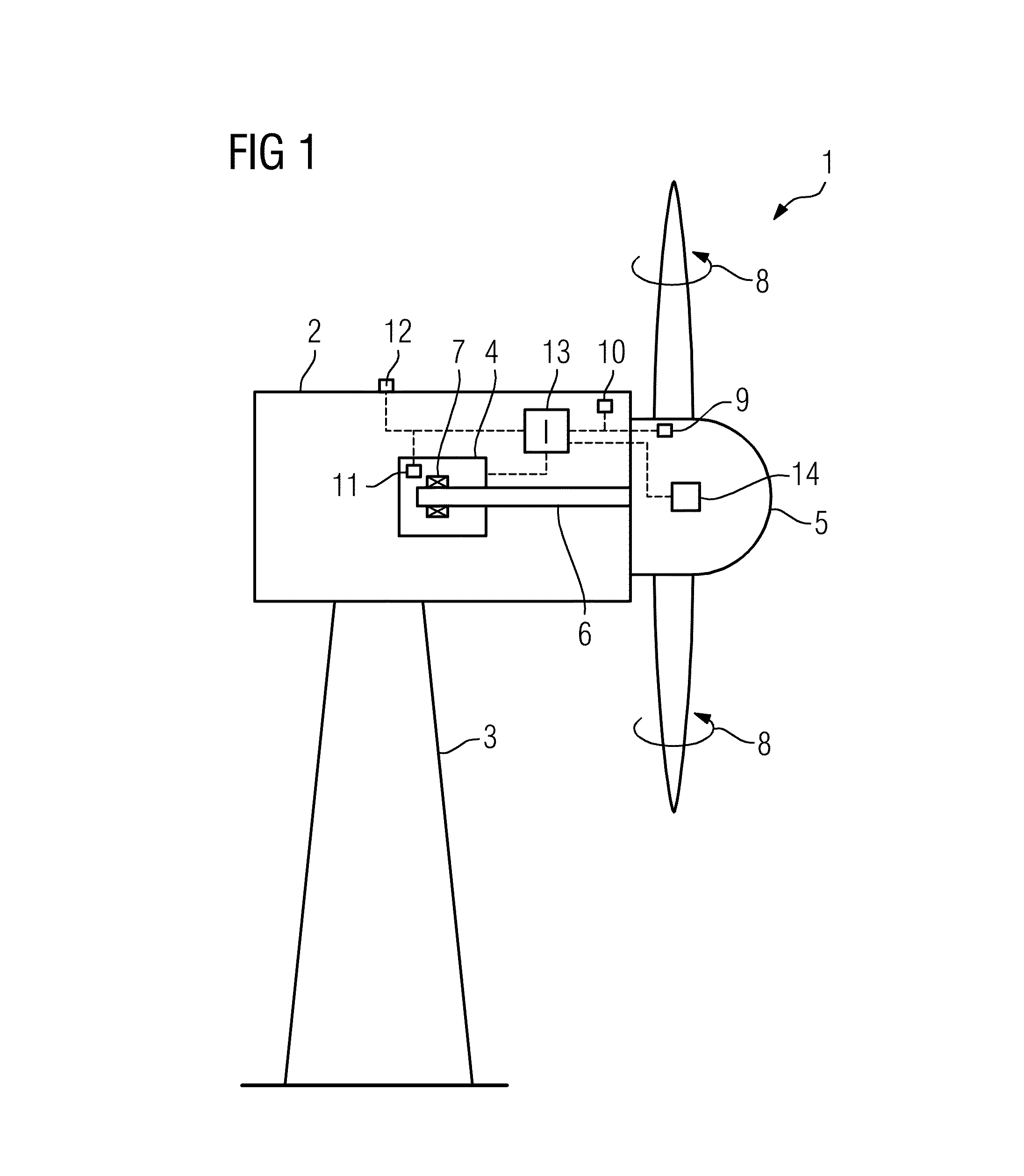
[0034]FIG. 1 shows a principle drawing of an embodiment of a wind turbine 1. The wind turbine 1 comprises a nacelle 2 disposed on a tower construction 3. The nacelle 2 houses a generator 4 which is directly connected to a rotor hub 5 by means of a central, direct or main shaft 6 which is rotatably supported relative to non-rotating components of the generator 4 such as the stator by means of a sliding bearing 7 (plain bearing). The rotor hub 5 comprises a number of rotor blades 6 attached thereto. As is indicated by arrows 8, the rotor blades 6 may be rotated around their longitudinal axis by means of a rotor blade pitch control means 14. The wind turbine 1 is disposed or anchored to ground or sea ground.

[0035]Several sensors 9-12 are provided with the wind turbine 1. Thereby, sensor 9 is capable of determining the rotational speed of the rotor hub 5, sensor 10 is capable of determining the torque on the shaft 6, sensor 11 is capable of determining the film thickness of the lubrican...


PUM


Abstract

Method for operating a wind turbine, comprising at least one generator and at least two components being rotatably supported relative to each other by means of at least one sliding bearing, whereby at least one operational state information of the wind turbine indicating the operational state of the wind turbine is determined, wherein the generator is operated as an electric motor for driving the wind turbine if the at least one operational state information indicates start-up or shut-down of the wind turbine.

Description

CROSS-REFERENCE TO RELATED APPLICATIONS[0001]This application claims priority to PCT / EP2012 / 071041, filed on Oct. 24, 2012, which claims priority to EP 11195347 filed Dec. 22, 2011, the disclosure of both are herewith incorporated by reference in their entireties.FIELD OF TECHNOLOGY[0002]The invention relates to a method for operating a wind turbine, comprising at least one generator and at least two components being rotatably supported relative to each other by means of at least one sliding bearing, whereby at least one operational state information of the wind turbine indicating the operational state of the wind turbine is determined.BACKGROUND[0003]It is known to provide components of the wind turbine being rotatably supported relative to each other with sliding or plain bearings instead of conventional rolling bearings. Sliding bearings show advantages in comparison to rolling bearings particularly regarding mechanical behaviour and life time.[0004]However, respective sliding be...

Claims


Application Information

Patent Timeline
IPC IPC(8): F03D7/04F03D11/00F03D9/00F03D7/02F03D1/06
CPCF03D7/042F03D7/0272F03D1/0675F03D7/026F03D7/0224F03D11/0008F03D9/002F03D7/0264F05B2270/32F05B2270/327F05B2270/335F03D80/70F03D9/25Y02E10/72F03D15/20
Inventor PEDERSEN, BOTHOMSEN, KIM
Owner SIEMENS AG
Learn More