Glass Furnace with Bottom Material Feed

a glass furnace and bottom material technology, applied in the field of glass furnaces with bottom material feed, can solve the problems of poor conductivity of dry batch materials, disturbance of dry materials by glass burner flames, and difficulty in operation, so as to reduce increase the efficiency of the furnace, and increase the amount of heat energy

Active Publication Date: 2015-10-29
OWENS-BROCKWAY GLASS CONTAINER INC
View PDF9 Cites 18 Cited by
  • Summary
  • Abstract
  • Description
  • Claims
  • Application Information

AI Technical Summary

Benefits of technology

[0001]The present disclosure is directed to an arrangement for feeding glass batch material into a furnace at a location below glass melt level to eliminate problems associated with the batch blanket that is otherwise formed on the top surface of the glass melt.

Problems solved by technology

Adding the raw batch materials into a glass furnace in this manner presents several operational difficulties.
First, the dry batch materials are poor conductors of heat due to their low heat transfer coefficients and radiation emissive factors.
Another issue is the disturbance of the dry materials by the glass burner flames.
The flow of air from the flames causes turbulence that disturbs and picks up the dry materials.
The dry materials become entrained in the exhaust gases that exit the furnace flue or stack, a situation referred to as ‘batch carryover’, resulting in environmental air emissions such as opacity and particulate matter emissions.
A third issue caused by the blanket of dry batch materials is the loss of light chemical elements such as sodium from the glass melt due to volatilization of these light elements.
The loss of batch materials due to carryover or volatilization alters the chemistry of the glass melt, resulting in a final glass chemistry that is outside of the desired chemical specification, which alters the properties of the final glass product.
Although batch wetting mitigates many of the problems discussed herein, it can cause others such as poor batch transport conditions, segregation, and additional energy consumption in the glass melting furnace to drive off the added water.

Method used


Image

  • Glass Furnace with Bottom Material Feed
  • Glass Furnace with Bottom Material Feed
  • Glass Furnace with Bottom Material Feed

Examples


Embodiment Construction

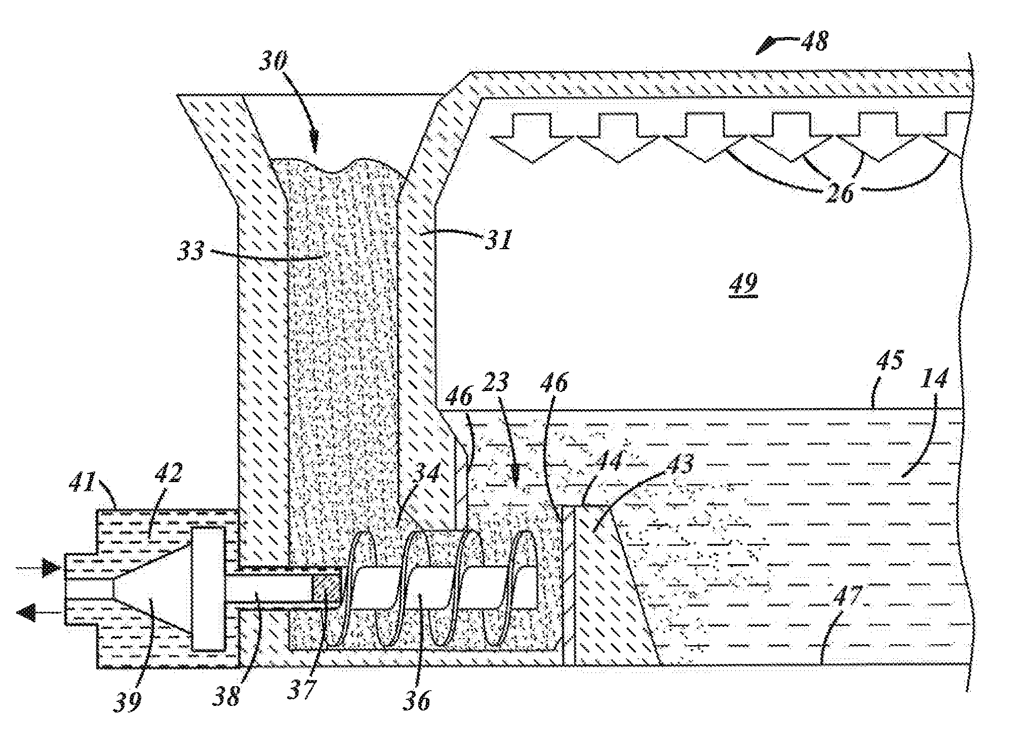
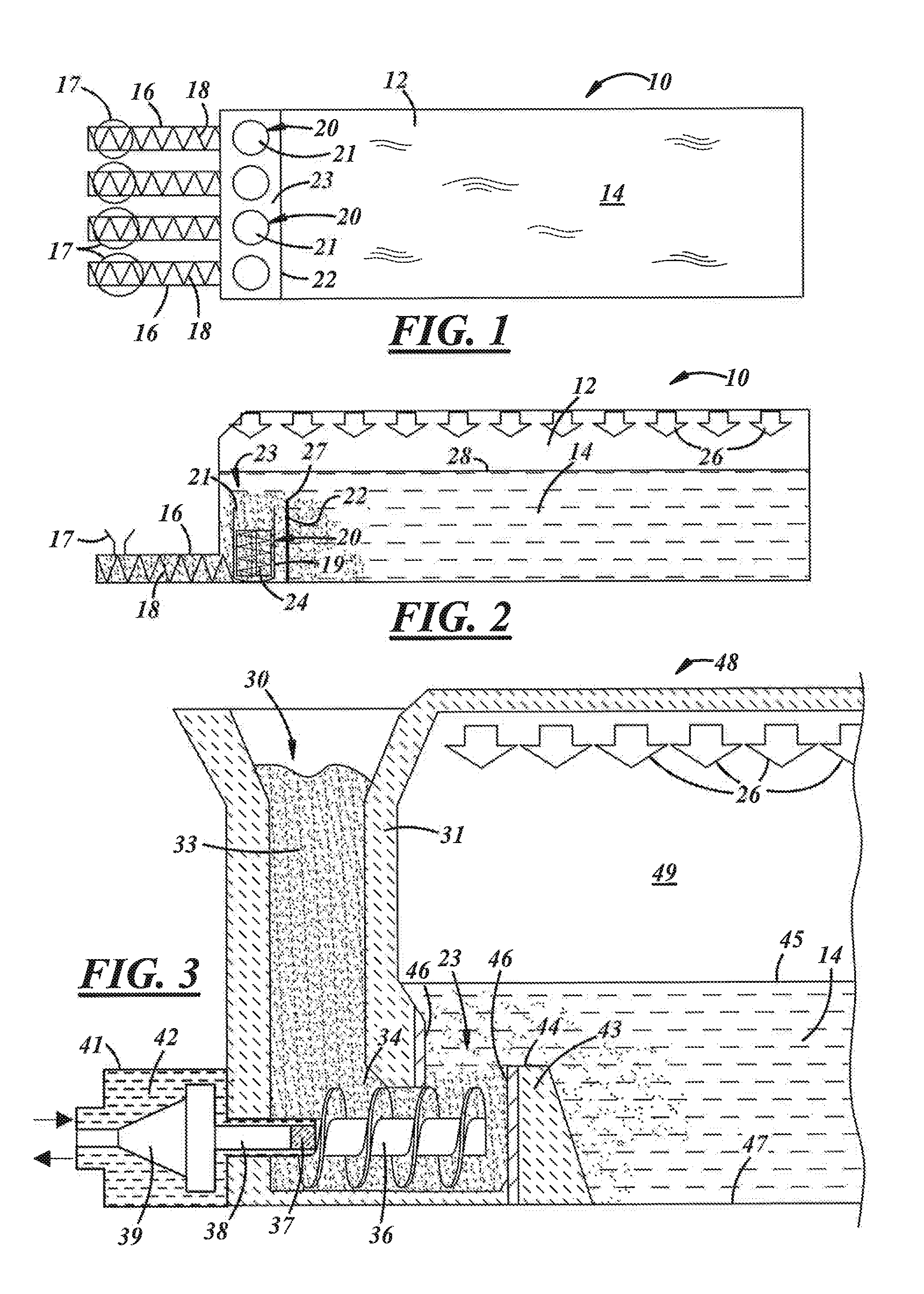
[0019]FIG. 1 illustrates a schematic top view of a glass melting furnace generally designated by the reference numeral 10. The furnace has a furnace melt chamber 12 for melting the raw batch materials which in operation contains a pool 14 of molten glass as understood by those skilled in the art. One or more batch feed chutes 16 may be connected to the furnace 10, for example, at a bottom portion thereof. A batch feed inlet 17 may be coupled to each batch feed chute 16 for the introduction of raw batch materials to the feed chute. Each of the batch feed chutes 16 may contain a batch feeder such as a screw conveyor 18. Each of the batch feed chutes 16 may be coupled to a heater 20 having an outlet 21 as more fully described below. A dam wall 22 may be disposed between the screw conveyor 18 and the melt chamber 12. The dam wall 22 creates a well 23 or a series of wells prior to the melt chamber 12 and may contain the heaters 20. The dam wall 22 may be positioned between the heater out...


PUM

PropertyMeasurementUnit
grain sizeaaaaaaaaaa
melt levelaaaaaaaaaa
thermal resistanceaaaaaaaaaa

Abstract

A glass furnace includes a furnace chamber for containing glass melt and a screw conveyor for receiving glass batch material and feeding the glass batch material to the furnace chamber. A dam wall is disposed with respect to the screw conveyor such that batch material from the screw conveyor must flow upward over the dam wall before entering the furnace chamber. The top of the dam wall may be below the level of the melt pool in the furnace chamber.

Description

[0001]The present disclosure is directed to an arrangement for feeding glass batch material into a furnace at a location below glass melt level to eliminate problems associated with the batch blanket that is otherwise formed on the top surface of the glass melt.BACKGROUND AND SUMMARY OF THE DISCLOSURE[0002]Typically, the natural gas burners that provide energy for a glass melting furnace, are located in the walls of the furnace. The flames from the burners extend across the width or the length of the furnace, slightly above and approximately parallel to the top surface of the glass melt within the furnace. Heat energy is transferred from the burner flames to the top surface of the glass melt primarily by conduction and radiation. In a typical furnace, raw batch materials are added to the furnace by distributing the raw materials on top of the existing glass melt, creating a batch ‘blanket’ of raw materials on the top surface of the glass melt. The raw batch materials consist of dry ...

Claims


Application Information

Patent Timeline
Patent Type & Authority Applications(United States)
IPC IPC(8): C03B3/02C03B3/00
CPCC03B3/005C03B3/023C03B3/026C03B5/04C03B5/2356Y02P40/50C03B3/00
Inventor WANG, ZHONGMINGWEIL, SCOTTGULLINKALA, TILAKVEMPATI, UDAYAKADUR, SHIVAKUMAR S.
Owner OWENS-BROCKWAY GLASS CONTAINER INC
Why Eureka
Try Eureka