
Wind turbine

a technology of wind turbines and bearings, which is applied in the direction of bearing units, rigid supports, machines/engines, etc., can solve the problem of putting an additional load on the yaw bearing, and achieve the effect of uniform manufacturing and comparatively easy production

Active Publication Date: 2015-10-29
WOBBEN PROPERTIES GMBH
View PDF7 Cites 14 Cited by
  • Summary
  • Abstract
  • Description
  • Claims
  • Application Information

AI Technical Summary

Benefits of technology

The patent describes a new way of positioning a wind turbine's yaw bearing and nacelle, which allows for better protection of the bearing and reduces the need for ventilation openings in the nacelle. The new system uses a shaft section that allows for the transfer of outside air for cooling purposes, while avoiding the need for air from close to the ground. This design offers more freedom in nacelle design and strengthens the overall performance of the wind turbine.

Problems solved by technology

This type of yaw bearing has to withstand enormous forces because it has to support the entire nacelle.
Wind pressure on the wind energy plant rotor can also add to the load causing a tilting moment, and therefore putting an additional load onto the yaw bearing.

Method used


Image

  • Wind turbine
  • Wind turbine
  • Wind turbine

Examples


Embodiment Construction

[0035]Below, similar elements may be described with similar but not identical embodiments to illustrate overall functionality using the same reference numbers.

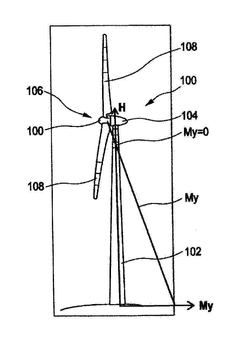
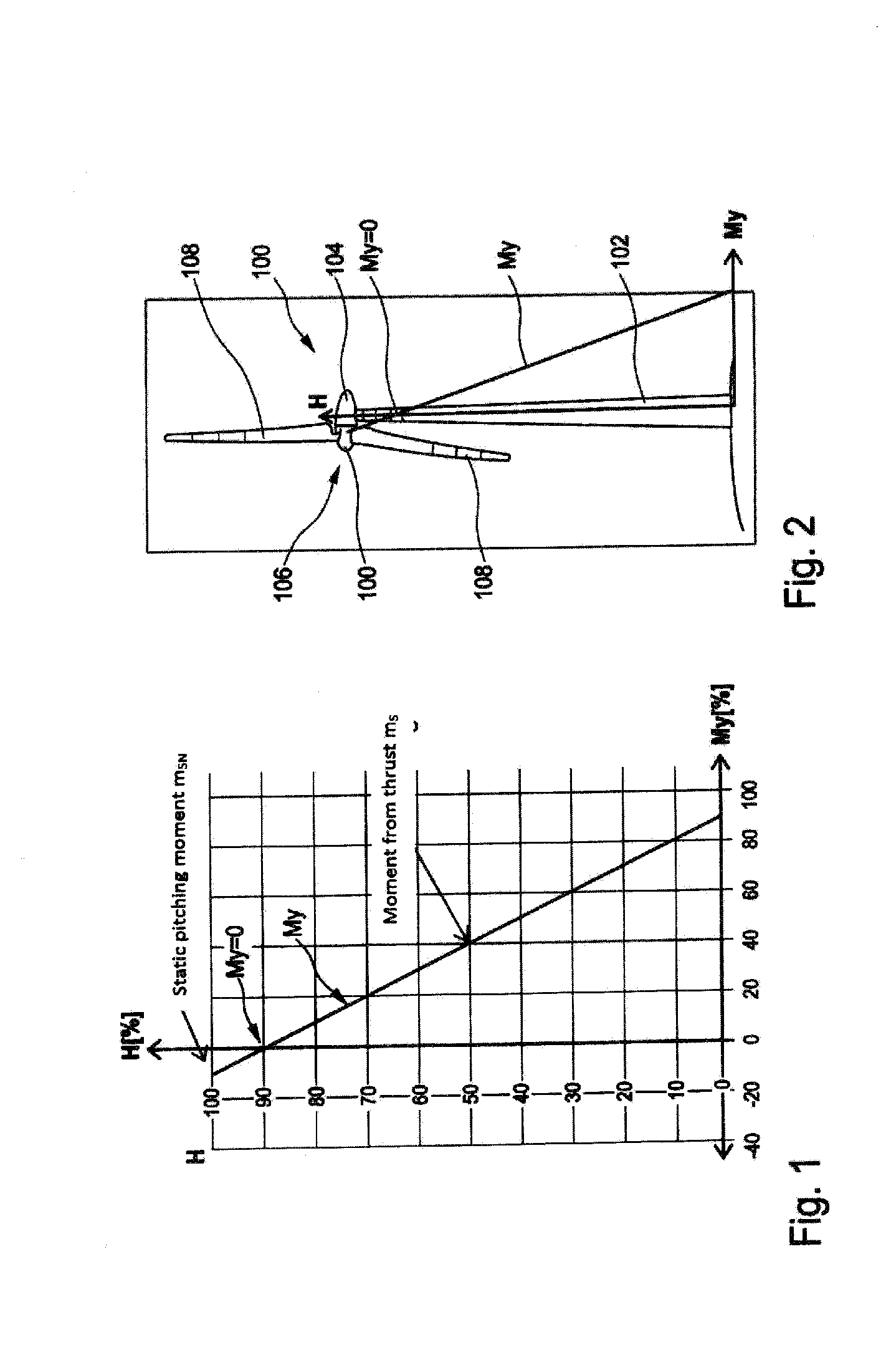
[0036]The diagram in FIG. 1 shows the tower bending moment My as a function of height. Here, the bending moment My can also be referred to as tower collective My. However, to better illustrate it, the bending moment My on the abscissa and the tower height on the ordinate are removed. The bending moment My is therefore shown in scale to the maximum thrust moment in % and the height is scaled to the overall tower height as a %. The diagram in FIG. 1 is an illustration and therefore shows a linear pathway of bending moment My.

[0037]It should be clear to see, or be illustrated by the diagram, that the bending moment is greatest at the base of the tower, i.e., at height H=0. The value here is approximately 90% and it should be illustrated that the 100% value of the thrust moment will not be reached because the pitching moment must ...


PUM


Abstract

The invention relates to a wind energy plant with a nacelle, a generator located in the nacelle, a tower and a yaw bearing to adjust the nacelle orientation into the wind, such that the yaw bearing is located under the nacelle in a vertical yaw displacement and the nacelle is supported on the yaw bearing above a vertical shaft section of the same length as the yaw displacement.

Description

BACKGROUND[0001]1. Technical Field[0002]This invention relates to a wind turbine or wind energy plant and a shaft section of a wind energy plant and a method for designing a wind energy plant.[0003]2. Description of the Related Art[0004]Wind energy plants or wind turbines are well known and convert wind energy into electrical energy. A typical wind energy plant has a tower with a nacelle on it, which contains an aerodynamic rotor and an electric generator. The nacelle is mounted on a yaw bearing in order to be able to turn on a horizontal plane, so that the angle of the yaw can be adjusted to the wind. This type of yaw bearing has to withstand enormous forces because it has to support the entire nacelle. This type of nacelle can weigh several hundred tons depending on the construction. Wind pressure on the wind energy plant rotor can also add to the load causing a tilting moment, and therefore putting an additional load onto the yaw bearing.[0005]The European patent application EP 1...

Claims


Application Information

Patent Timeline
IPC IPC(8): F03D11/00F03D11/04F03D7/02F03D1/00F03D9/00
CPCF03D11/0008F03D1/00F03D11/04F03D9/002F03D7/0204F03D11/0058Y02E10/728F05B2240/912F05B2260/64Y02E10/72F03D80/70F03D80/82F03D13/20F03D9/25F16C2360/31F16C35/06F03D7/02F03D80/88F03D80/00
Inventor ROER, JOCHENHOFFMANN, ALEXANDER
Owner WOBBEN PROPERTIES GMBH
Learn More