
Low-noise magnetic resonance imaging using low harmonic pulse sequences

a low-noise, pulse sequence technology, applied in the direction of magnetic measurements, instruments, measurement devices, etc., can solve the problems of limiting the use of other types of available contrast, acoustic noise, and inherent proton-density contras

Active Publication Date: 2015-10-29
GENERAL ELECTRIC CO
View PDF3 Cites 9 Cited by
  • Summary
  • Abstract
  • Description
  • Claims
  • Application Information

AI Technical Summary

Benefits of technology

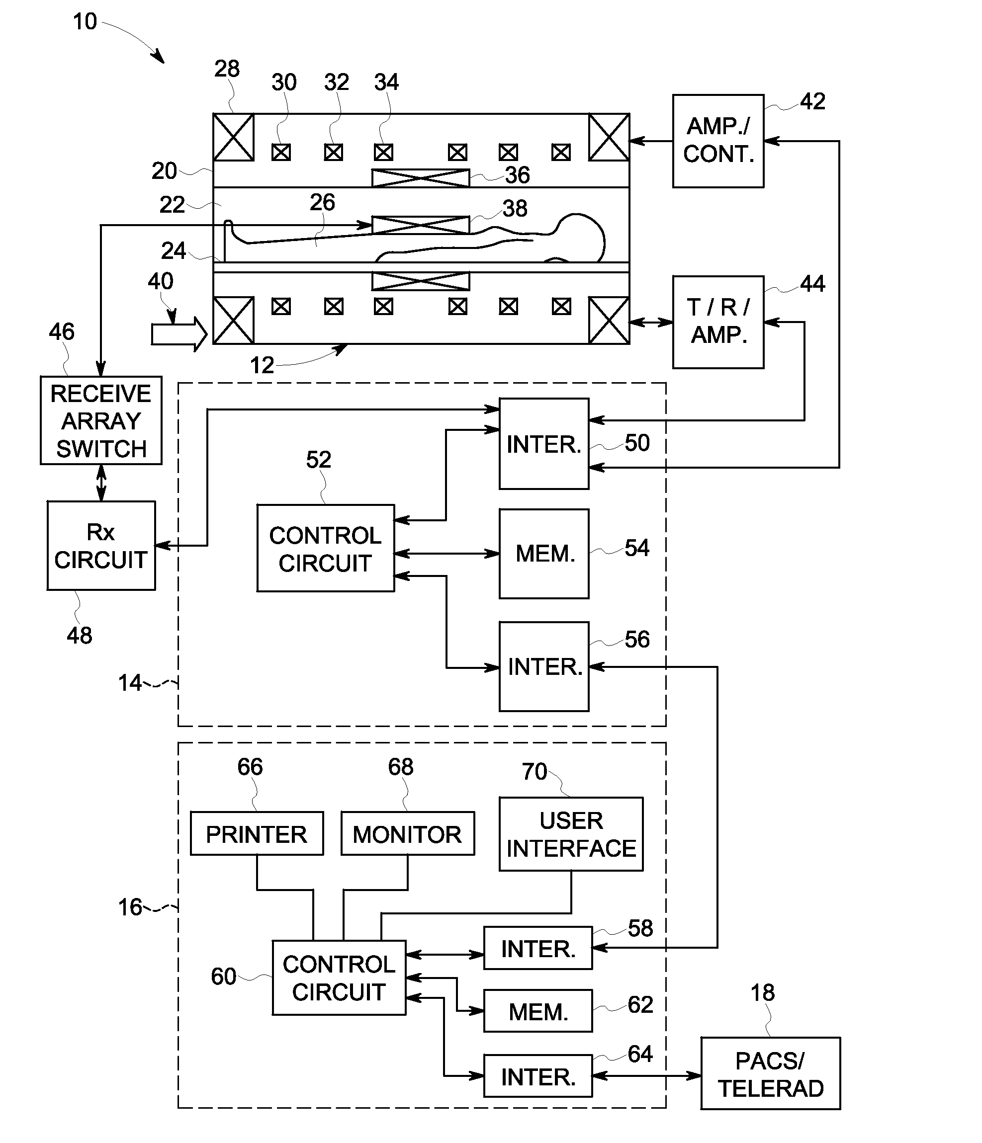
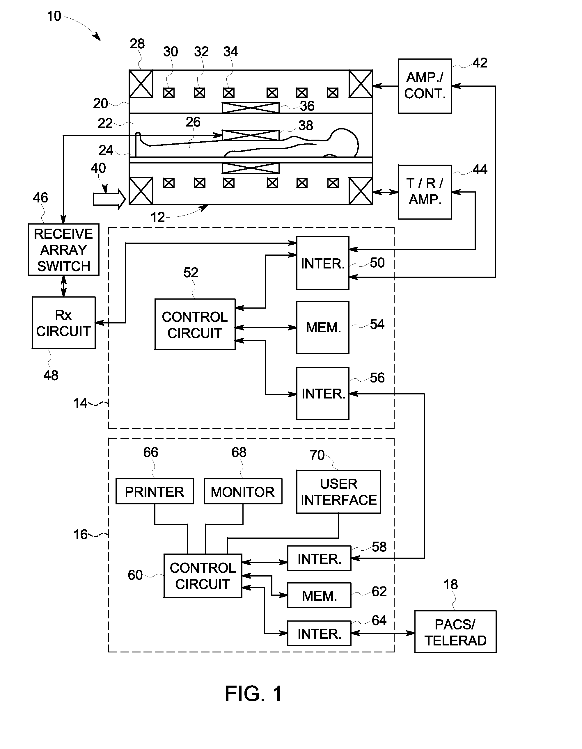
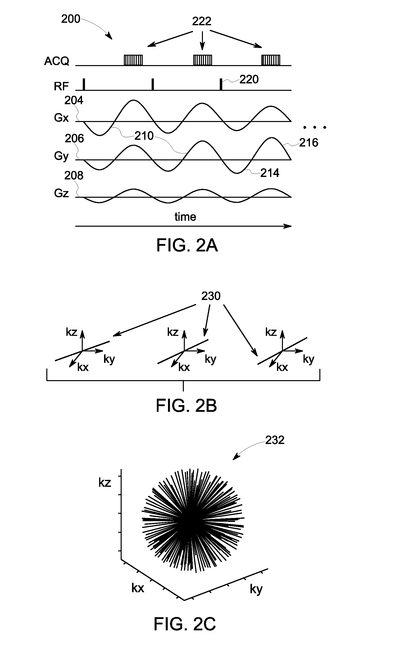
This patent describes a method and system for driving gradient coils in a magnetic resonance imaging system. The method includes driving each of the gradient coils with a unique sinusoidal gradient waveform to generate RF pulses at crossover events, where the gradient waveforms cross their respective gradient zero lines. The resulting image has improved quality and accuracy. The technical effects of this patent include improved image quality, reduced noise, and improved magnetic resonance imaging of the brain and other organs.

Problems solved by technology

In practice, driving the gradient coils may result in substantial amounts of acoustic noise due to the waveforms employed and the manner in which these waveform interact acoustically.
One current approach for low-noise MRI may utilize very low tip angle excitation pulses, which results in inherent proton-density contrast and which constrains the use of other types of available contrast.
To address these issues, some approaches employ spin-preparation sequences to expand the range of available contrast, but such approaches involve added complexity and scan duration.

Method used


Image

  • Low-noise magnetic resonance imaging using low harmonic pulse sequences
  • Low-noise magnetic resonance imaging using low harmonic pulse sequences
  • Low-noise magnetic resonance imaging using low harmonic pulse sequences

Examples


Embodiment Construction

[0019]One or more specific embodiments will be described below. In an effort to provide a concise description of these embodiments, all features of an actual implementation may not be described in the specification. It should be appreciated that in the development of any such actual implementation, as in any engineering or design project, numerous implementation-specific decisions must be made to achieve the developers' specific goals, such as compliance with system-related and business-related constraints, which may vary from one implementation to another. Moreover, it should be appreciated that such a development effort might be complex and time consuming, but would nevertheless be a routine undertaking of design, fabrication, and manufacture for those of ordinary skill having the benefit of this disclosure.

[0020]When introducing elements of various embodiments of the present invention, the articles “a,”“an,”“the,” and “said” are intended to mean that there are one or more of the ...


PUM


Abstract

Systems and method for magnetic resonance imaging are disclosed which utilize sinusoidal gradient waveforms to drive gradient coils in an MRI system. The sinusoidal gradient waveforms may be applied on all two or more (e.g. three) gradient axes to produce a relatively pure acoustic tone. In certain embodiments, gradient directions may be spiraled in three-dimensions to generate a radial pin-cushion k-space trajectory

Description

BACKGROUND[0001]In general, magnetic resonance imaging (MRI) examinations are based on the interactions among a primary magnetic field, a radiofrequency (RF) magnetic field, and time varying magnetic gradient fields with a gyromagnetic material having nuclear spins within a subject of interest, such as a patient. Certain gyromagnetic materials, such as hydrogen nuclei in water molecules, have characteristic behaviors in response to external magnetic fields. The precession of spins of these nuclei can be influenced by manipulation of the fields to produce RF signals that can be detected, processed, and used to reconstruct a useful image.[0002]The magnetic fields used to generate images in MRI systems include a highly uniform, static magnetic field that is produced by a primary magnet. A series of gradient fields are produced by a set of gradient coils located around the imaging volume in which the subject is placed. The gradient fields encode positions of individual plane or volume e...

Claims


Application Information

Patent Timeline
IPC IPC(8): G01R33/565G01R33/38G01R33/36G01R33/34
CPCG01R33/56572G01R33/36G01R33/3808G01R33/34092G01R33/3854G01R33/4826G01R33/5616G01R33/5617
Inventor HARDY, CHRISTOPHER JUDSONMCKINNON, GRAEME COLIN
Owner GENERAL ELECTRIC CO
Learn More