System and Apparatus for a Laboratory Scale Reactor

a laboratory scale and reactor technology, applied in the field of laboratory scale reactor systems and apparatuses, can solve the problems of high cost, increased time consumption, and increased maintenance costs of laboratory scale reactors

Inactive Publication Date: 2015-11-05
CLEAN DIESEL TECHNOLOGIES
View PDF1 Cites 10 Cited by
  • Summary
  • Abstract
  • Description
  • Claims
  • Application Information

AI Technical Summary

Benefits of technology

[0009]The method may include isolating the load perceived by the heating elements from the loading perceived by the catalyst being tested, where excess gas may undergo any suitable venting, including venting over a catalyst holder, venting to a confined environment, venting to the general environment, or any suitable combination. This may allow the space-velocity of gas processed by the heater to vary from the space-velocity of the gas flowing through the sample.
[0011]The method may also include using separate banks of mass flow controllers for mixing the gas composition to the desired composition and for controlling the flow of the gas composition through the heater. A separate bank may be used for controlling any suitable mix of reducing agents, nitric oxide, and diluent gas; while another separate bank may be used for controlling any suitable mix of oxidizing gases, carbon dioxide, and diluent gas. The flow of gas through each bank may be controlled so as to result in any suitable gas composition, including embodiments where the amount of gas flowing through each bank may be controlled to be about half of the flow, where the amount of gas flowing through each bank may be regulated by regulating the amount of diluent gas flowing through each bank. Embodiments where each of the banks may contribute about half of the flow may allow the events that may be generated in each of the banks to reach the catalyst sample at about the same time.

Problems solved by technology

Devices of use in testing catalysts may include one or more combustion engines; however, the use of these engines may be expensive, require higher maintenance than desired, and be more time consuming.
Additionally, the use of these engines may not allow individual parameter variations or calibrations of use when testing catalysts.
However, Laboratory-scale reactors may not capture the catalyst's response to dynamic changes in one or more of multiple variables, including temperature, space-velocity, and reactant gas concentration.

Method used


Image

  • System and Apparatus for a Laboratory Scale Reactor
  • System and Apparatus for a Laboratory Scale Reactor
  • System and Apparatus for a Laboratory Scale Reactor

Examples


Embodiment Construction

Definitions

[0020]As used here, the following terms have the following definitions:

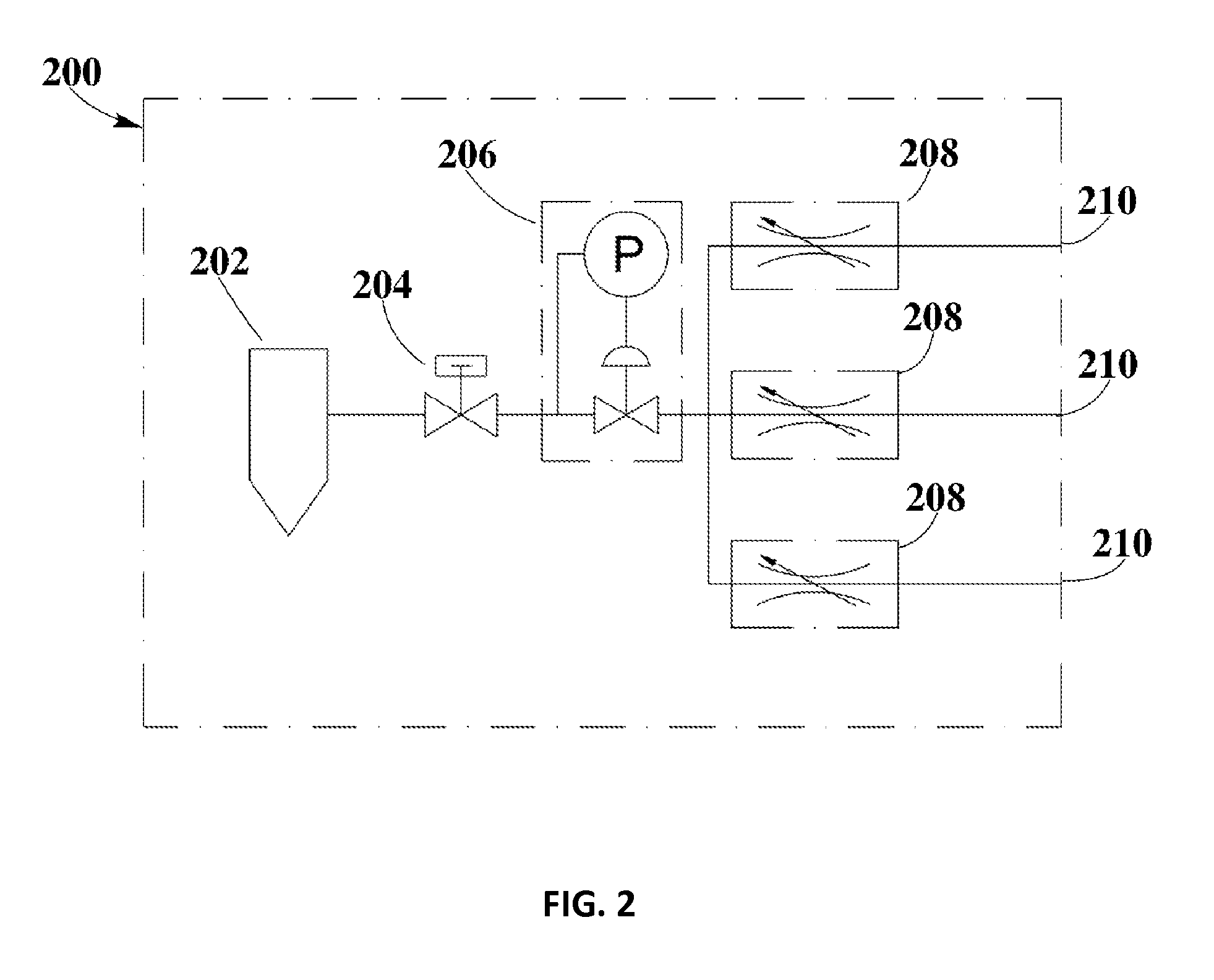
[0021]Mass flow controller (MFC) refers to any computer controlled analog or digital device of use in controlling the flow rate of fluids and / or gases.

[0022]Temperature controller refers to any device of use in controlling temperature in a process.

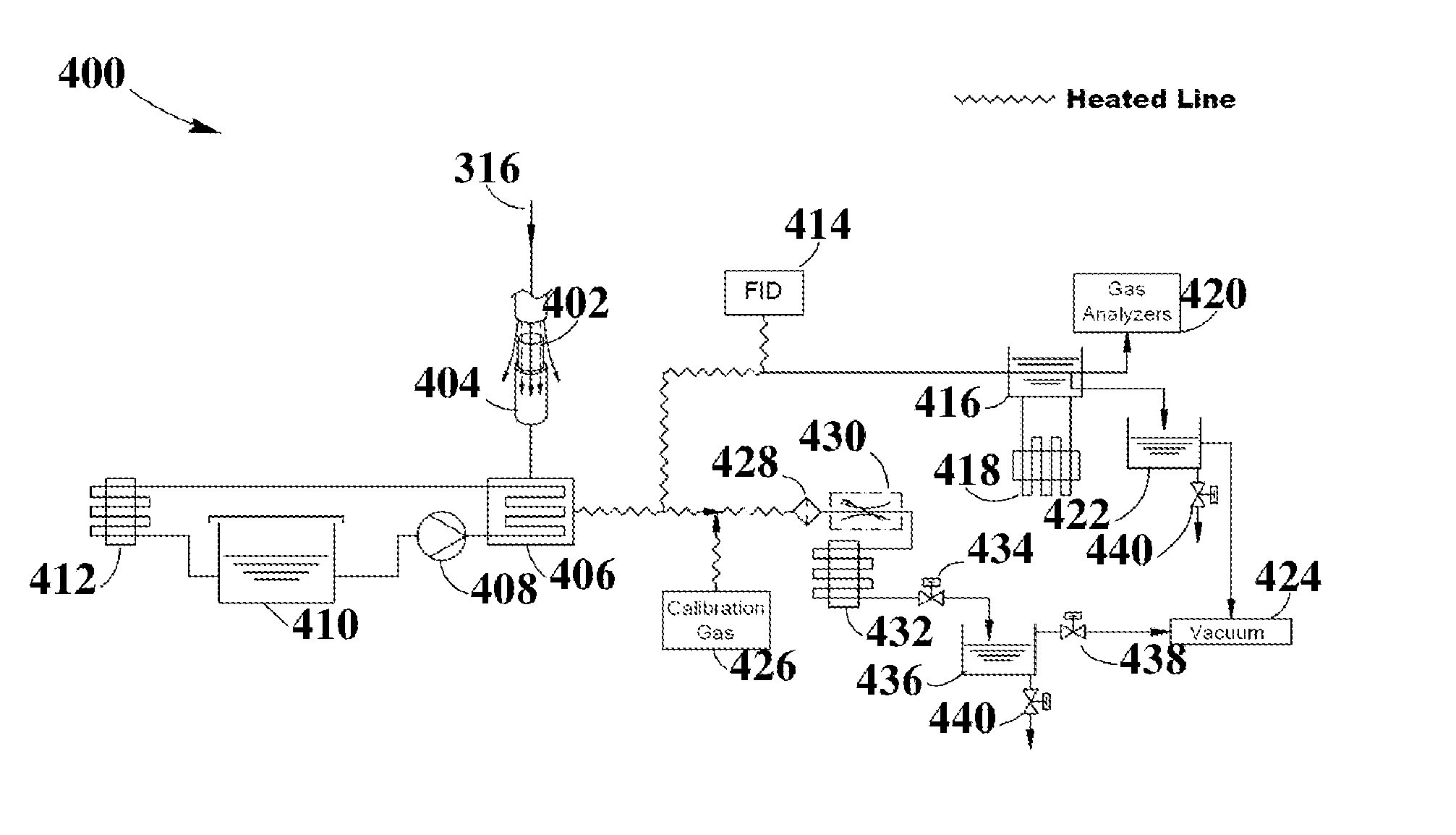
[0023]Laboratory Scale Reactor / Test Bench refers to any apparatus suitable for testing a material with a test gas.

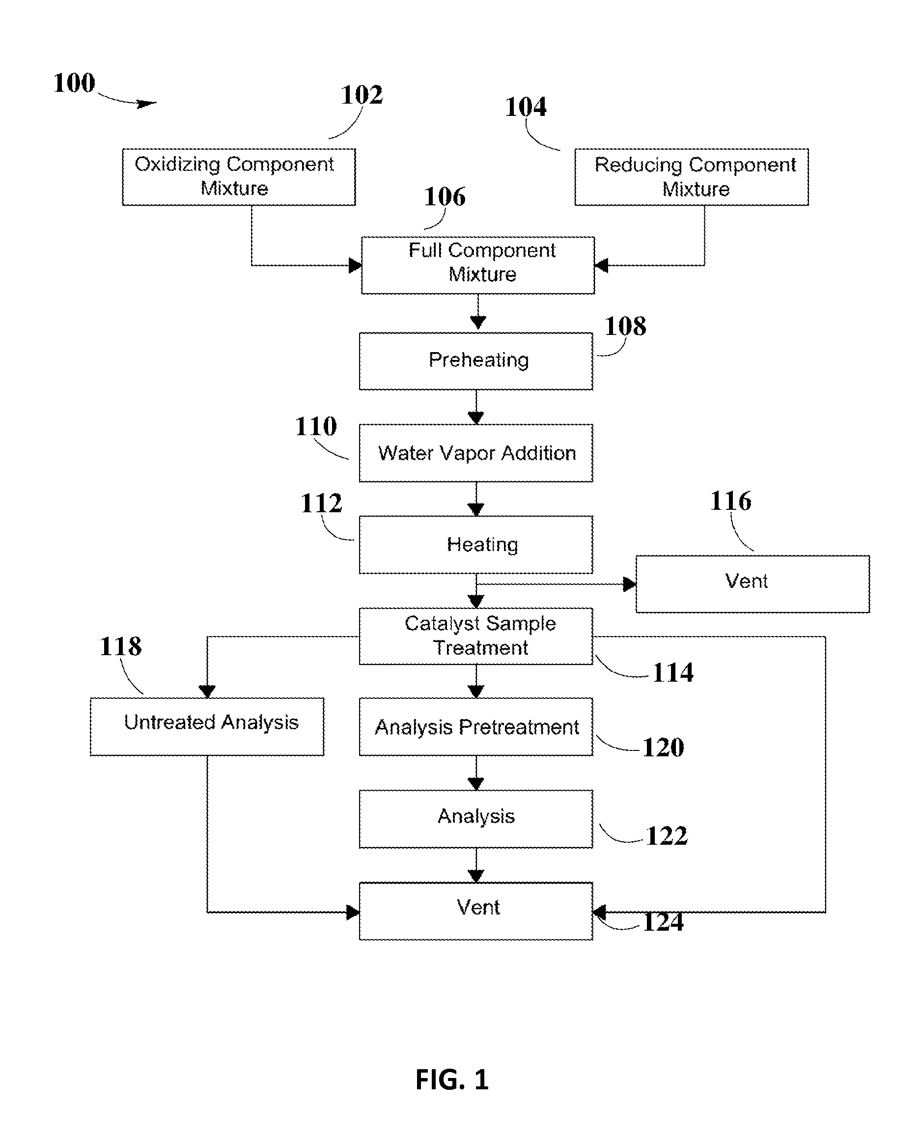
[0024]Oxidizing agent refers to any substance that may take electrons from another substance in a redox chemical reaction.

[0025]Reducing agents refers to any substance that may give electrons to another substance in a redox chemical reaction.

[0026]Gas mixture refers to the mixture obtained from combining oxidizing agents, reducing agents, inert gases, or any other suitable gases.

[0027]Water-gas mixture refers to the mixture obtained from combining water vapor with a gas mixture.

[0028]Test Gas refers to any gas mixture of use in chemically testing ...


PUM

PropertyMeasurementUnit
temperatureaaaaaaaaaa
frequenciesaaaaaaaaaa

Abstract

The present disclosure may include a device for testing catalysts, and a method for controlling the flow rate and temperature parameters during the process. The device may separate mass flow control through heating elements from the mass flow through the sample, as well as separate banks for mixing oxidizing elements, carbon dioxide, and diluent gas as well as reducing agents, nitric oxide, and diluent gas. The device disclosed here may also use mass control units of a sufficiently high speed so as to allow the desired testing conditions.

Description

CROSS-REFERENCE TO RELATED APPLICATIONS[0001]This application is a continuation of U.S. Ser. No. 13 / 891,758, U.S. Ser. No. 13 / 891,773, and U.S. Ser. No. 13 / 891,745, each filed on May 10, 2013 and incorporated herein by reference as if set forth in their entireties.BACKGROUND[0002]1. Field of the Disclosure[0003]The present disclosure relates to a laboratory test device and, more particularly, to a device for testing catalysts under dynamic conditions.[0004]2. Background Information[0005]Catalysts may need to be tested to evaluate their performance and their response to parameter changes. Devices of use in testing catalysts may include one or more combustion engines; however, the use of these engines may be expensive, require higher maintenance than desired, and be more time consuming. Additionally, the use of these engines may not allow individual parameter variations or calibrations of use when testing catalysts. Other test devices suitable for testing catalysts may include Laborat...

Claims


Application Information

Patent Timeline
Patent Type & Authority Applications(United States)
IPC IPC(8): G01N33/00
CPCG01N33/0073G01N31/10
Inventor HATFIELD, RANDAL L.
Owner CLEAN DIESEL TECHNOLOGIES
Why Eureka
Try Eureka