High throughput propylene from methanol catalytic process development method

a technology of propylene and methanol, which is applied in the direction of catalyst regeneration/reactivation, physical/chemical process catalysts, bulk chemical production, etc., can solve the problems of sequential approach that typically takes over three years to complete, low reaction rate, and selectivity loss, and achieve high propylene productivity and selectivity, and low cost

Inactive Publication Date: 2010-07-08
BAUMAN RICHARD F +1
View PDF3 Cites 10 Cited by
  • Summary
  • Abstract
  • Description
  • Claims
  • Application Information

AI Technical Summary

Benefits of technology

[0018]This invention relates to a low cost, accelerated method for determining an advantageous combination of reactor structures, catalyst characteristics, catalyst bed structures and process conditions for scaling up from discovery to commercial readiness a plug-flow catalytic process for producing propylene from methanol (and/or DME) having high propylene productivity and selectivity and minimizing production of heavy (C5+) hydrocarbons, catalys

Problems solved by technology

The larger particle size generally results in a lower reaction rate and a selectivity loss due to limitations on mass transfer of reactants or products in and out of the catalyst pores.
This sequential approach typically takes in excess of three years to complete and may not provide all of desired data.
This approach is useful for comparing the intrinsic properties of an array of candidate catalysts but does not provide the data required for scale-up.
Although good yields of ethylene and propylene were reported in this '263 patent, they unfortunately were accompanied by substantial formation of higher aliphatic and aromatic hydrocarbons, which the patentees speculated might be useful as an engine fuel and specifically as a gasoline-type of material.
The '3

Method used


Image

  • High throughput propylene from methanol catalytic process development method
  • High throughput propylene from methanol catalytic process development method
  • High throughput propylene from methanol catalytic process development method

Examples


Embodiment Construction

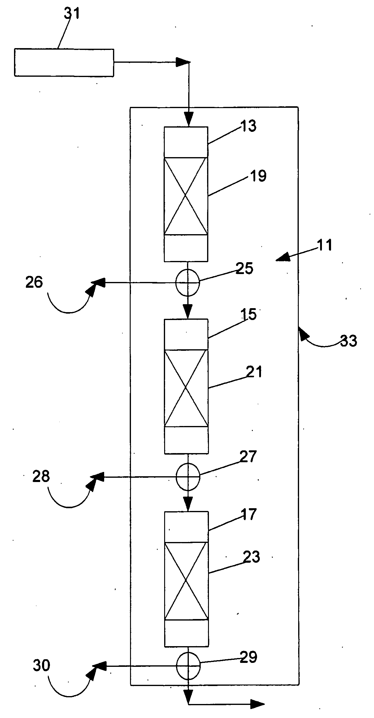
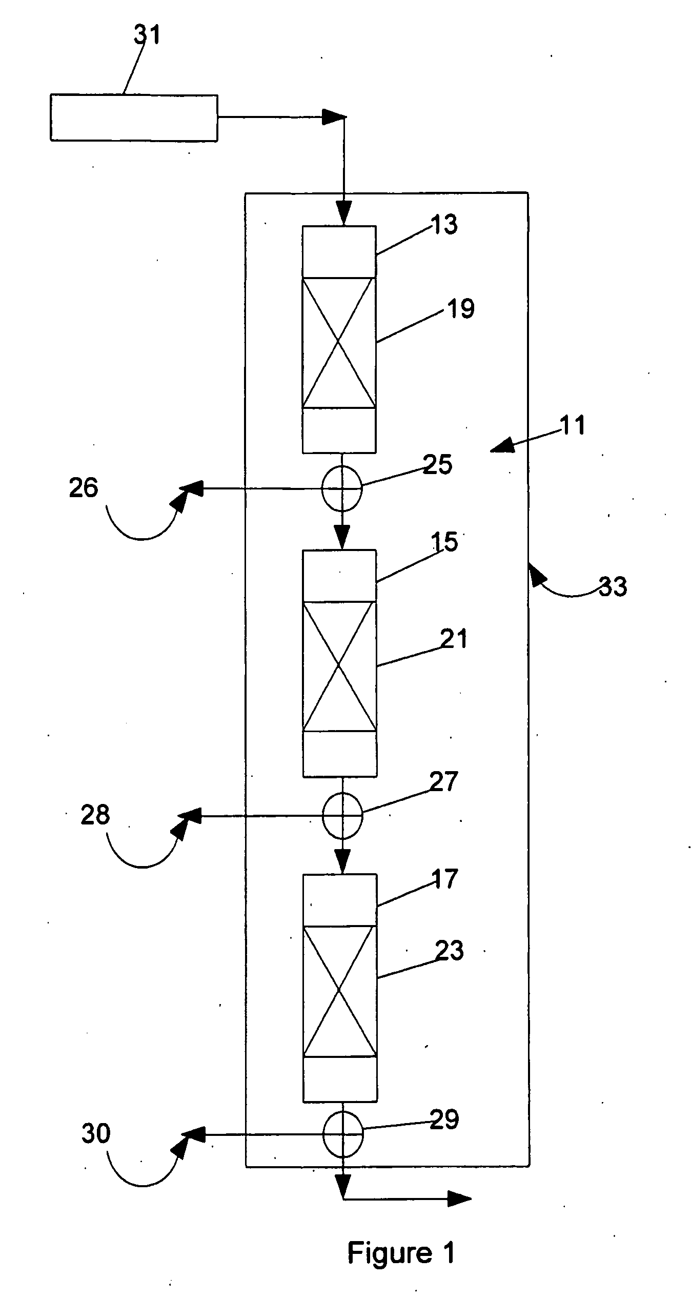
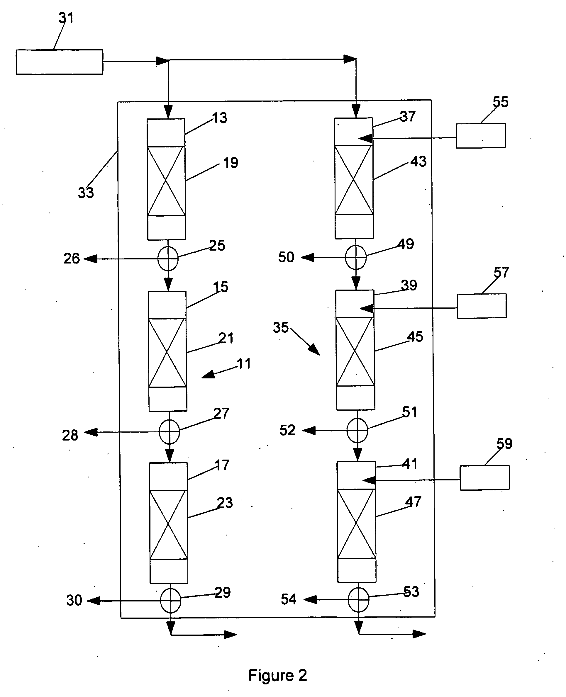
[0039]In the conversion of methanol and / or DME to propylene, it is desirable to the extent practicable to maximize the productivity and selectivity to propylene and the ratio of propylene to ethylene, and to minimize the production of higher molecular weight (C5+) hydrocarbons. It is also important to minimize to the extent practicable the deactivation of the zeolite containing catalysts in the series-connected plug-flow reactors used in the process. An important component of this deactivation results from the carbon overlayer formation on the catalyst surface. The degree of difficulty involved in regenerating the zeolite containing catalysts by removing the carbon overlayer is also an important consideration in the commercial scale catalytic conversion system design.

[0040]The inventors have found that, in the conversion of methanol and / or DME to propylene in a plug-flow reactor system that includes a plurality of series-connected plug-flow reactors having catalyst beds preferably c...


PUM

PropertyMeasurementUnit
Pressureaaaaaaaaaa
Volumeaaaaaaaaaa
Electric chargeaaaaaaaaaa

Abstract

A catalytic process development apparatus and method for simulating a commercial scale methanol and/or DME to propylene catalytic conversion system that includes a plurality of series-connected plug-flow reactors. The method involves simulating the operation of the series-connected plug-flow reactors by operating a series of multistage series-connected laboratory scale plug-flow reactors, the stages of which each containing a zeolite catalyst bed, each of the laboratory scale reactors corresponding to a separate one of the commercial scale series-connected reactors. Fresh feed, including methanol and/or DME, is supplied to the first of the laboratory scale reactor stages, and selected ones of steam, methanol and/or DME, contaminants and reaction products are supplied to selected ones of the laboratory scale reactor stages. The simulation is repeated at different sets of operating conditions and catalyst characteristics.

Description

FIELD OF INVENTION[0001]This invention relates to methods for the low cost, accelerated development of methanol and / or dimethyl ether (“DME”) to propylene (DTP) catalysts and corresponding fixed bed catalytic processes from discovery to commercial readiness.BACKGROUND OF THE INVENTION[0002]In order to scale-up a fixed bed methanol (or DME) to propylene (MTP or DTP) catalytic process, it is necessary to define the impact of time on stream, residence time, catalyst particle size, shape and other characteristics, and temperature profile on reaction rate and selectivity, and deactivation rate of the catalyst.[0003]The first step in a traditional scale-up program generally involves the selection and definition of the intrinsic properties of the catalyst. This step is typically performed isothermally with a diluted, crushed or powdered catalyst to minimize mass transfer limitations. A process variable study is performed to determine the impact of space velocity, pressure, and residence ti...

Claims


Application Information

Patent Timeline
IPC IPC(8): C07C1/20
CPCB01J19/0046B01J19/0093C40B60/12B01J29/90B01J38/04B01J38/50B01J2219/00015B01J2219/00286B01J2219/00477B01J2219/00495B01J2219/00585B01J2219/0059B01J2219/00707B01J2219/00747B01J2219/00788B01J2219/00835B01J2219/0086B01J2219/00867B01J2219/00869B01J2219/00873B01J2219/00891B01J2219/00957B01J2219/00961B01J2219/00963B01J2219/00981C07C1/20C07C2529/06C07C11/06Y02P20/584Y02P20/52
Inventor BAUMAN, RICHARD F.FIATO, ROCCO A.
Owner BAUMAN RICHARD F
Why Eureka
Try Eureka