Oxidation process apparatus, oxidation method, and method for manufacturing electronic device

a technology of oxidation process and electronic device, which is applied in the direction of solid-state diffusion coating, vacuum evaporation coating, coating, etc., can solve the problems of more multi-layer, unstable element characteristics (mr ratio or ra distribution), and the above-mentioned technologies have problems, so as to reduce the amount of oxygen adsorbed, improve throughput, and reduce the mixing of impurities

Active Publication Date: 2015-11-05
CANON ANELVA CORP
View PDF4 Cites 9 Cited by
  • Summary
  • Abstract
  • Description
  • Claims
  • Application Information

AI Technical Summary

Benefits of technology

[0014]Moreover, unless a duration of stay of the oxygen gas in the oxidation process chamber is reduced, throughput slows down, which in turn leads to deterioration in productivity and hence to an increase in cost for a semiconductor device. There exists the problem of needing to perform an oxidation process for formation of a desired MgO film in a short time, while suppressing a reduction in the throughput. Further, the oxygen gas remains in the oxidation process chamber and hence a time for evacuation to a predetermined pressure after the oxidation process becomes long, and thus, the throughput may become slower. Moreover, adsorption of impurities on the interface leads to the problem of causing the occurrence of a crystal defect or deterioration in the characteristics in a metal multilayer film structure.
[0017]The present invention has been made in view of the foregoing problems. An object of the present invention is to provide an oxidation process apparatus, an oxidation method, and a method for manufacturing an electronic device, which, when oxidizing a substrate, enable reducing the amount of oxygen adsorbed on a wall which partitions an oxidation process space, improving throughput, and reducing mixing of impurities into a film (for example, a magnetic film) formed on the substrate subjected to an oxidation process.
[0020]According to the present invention, it is possible to, in oxidation of a substrate, reduce the amount of oxygen adsorbed on a wall which partitions an oxidation process space, improve throughput, and reduce mixing of impurities into a film (for example, a magnetic film) formed on the substrate subjected to an oxidation process.

Problems solved by technology

However, the above-mentioned technologies have problems as given below.
In the manufacturing method disclosed in Patent Document 1, a structure obtained by sputtering four kinds of materials, namely, Ta, Ru, CoFeB, and MgO, is disclosed as the multilayer film of the perpendicular magnetization type; however, higher density involves a more complicated STT-RAM multilayer structure and thus requires forming more multilayer films.
Also, if the RA distribution is poor, an MRAM element formed in a plane cannot be turned on and off, and thus, the MRAM does not function as memory.
Thus, there arises the problem of needing to increase the rate of resistance change and thereby further improve the in-plane RA distribution.
Thus, even if evacuation takes place, when the release of the oxygen gas from the wall which partitions the oxidation process space continues, element characteristics (an MR ratio or the RA distribution) are not stable.
In other words, an unintended oxidation process proceeds, so that the oxidation process is excessively performed.
Thus, the excessive oxidation process leads to deterioration in the MR ratio or the RA distribution.
Further, effective oxidation process time may vary from one oxidation process to another, which in turn leads to instability of the element characteristics such as the MR ratio or the RA distribution among fabricated elements.

Method used


Image

  • Oxidation process apparatus, oxidation method, and method for manufacturing electronic device
  • Oxidation process apparatus, oxidation method, and method for manufacturing electronic device
  • Oxidation process apparatus, oxidation method, and method for manufacturing electronic device

Examples


first embodiment

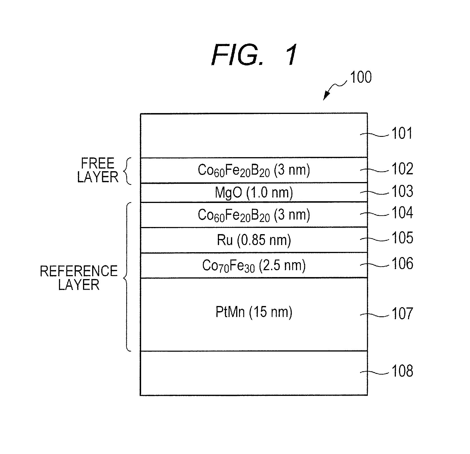
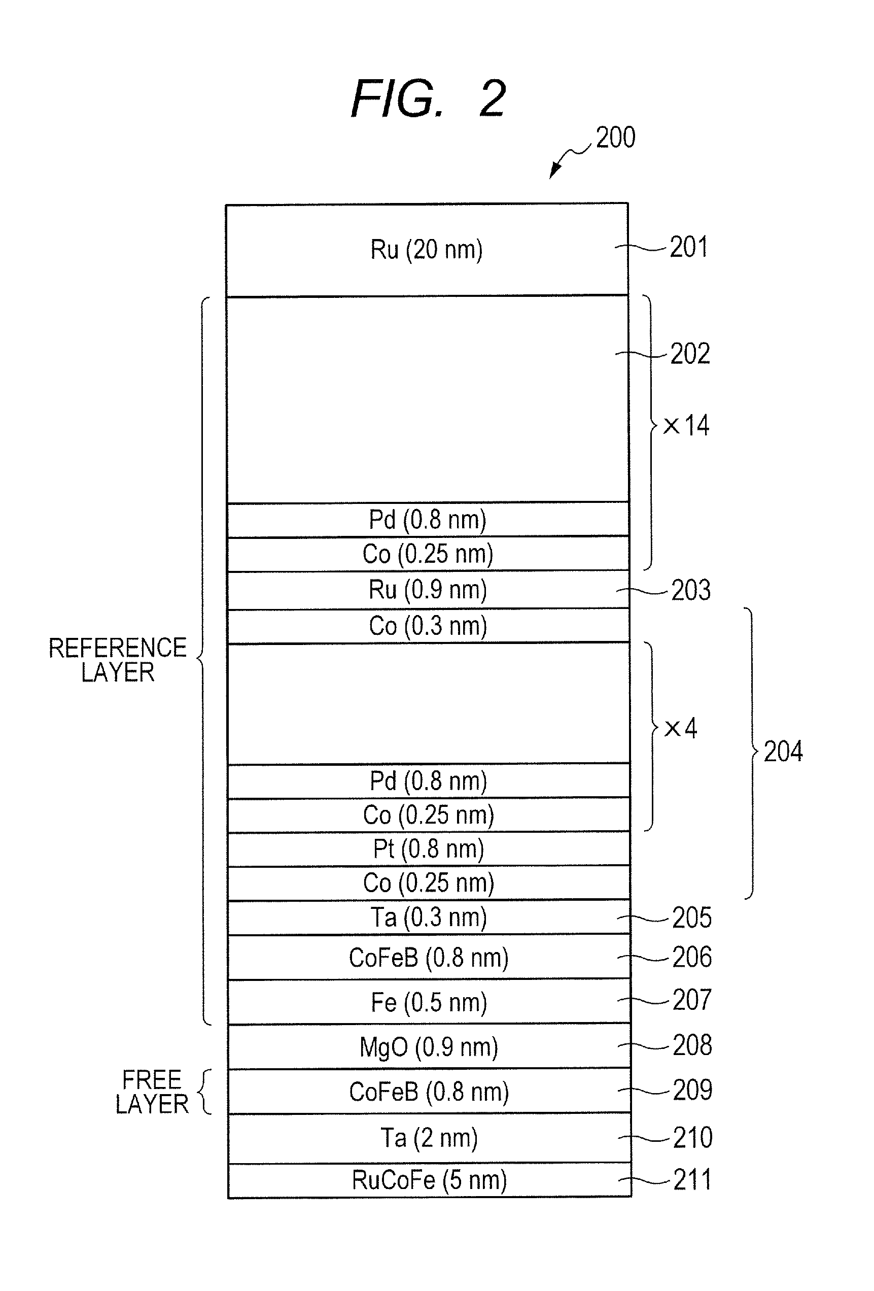
[0048]FIG. 4 is a schematic diagram illustrating a configuration of an oxidation process apparatus 400 according to the embodiment, under a substrate transport condition. FIG. 5 is a schematic diagram illustrating the configuration of the oxidation process apparatus 400 according to the embodiment, under an oxidation process condition. In the embodiment, the oxidation process apparatus 400 forms a barrier layer of each element illustrated by way of example in FIGS. 1 to 3. In the embodiment, the barrier layer is made of MgO, and a substrate having Mg formed thereon is subjected to an oxidation process in the oxidation process apparatus 400 thereby to form MgO.

[0049]In FIGS. 4 and 5, the oxidation process apparatus 400 includes a processing chamber 401, a vacuum pump 402 as an evacuation unit for evacuating the processing chamber, a substrate holder 404 configured to hold a substrate 403 placed in the processing chamber 401, a cylindrical member 405 disposed in the processing chamber...

first example

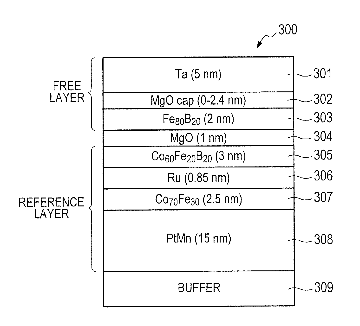
[0078]Description will be given below with regard to Example in which the oxidation process apparatus 400 according to the embodiment is used to form the barrier layer 304 of the tunnel magnetoresistive element 300 disclosed in FIG. 3 and Non Patent Document 3. A substrate temperature can be appropriately determined within a range of 25° C. to 500° C.; an oxygen gas flow rate, 1 to 2000 sccm; a substrate rotation speed, 0 to 100 rpm; and a substrate position, 0 to 100 mm (here, a condition where the substrate is located in the opening 405b of cylindrical member 405 is set to 0 mm). An oxidation process is performed, for example under a condition where the substrate temperature is set to 25° C.; the oxygen flow rate, 700 sccm; the substrate rotation speed, 100 rpm; and the substrate position, 100 mm.

second example

[0079]In this Example, studies were made on tact time in a case where the conventional oxidation process apparatus not using the cylindrical member 405 was used to perform the oxidation process, and tact time in a case where the oxidation process apparatus 400 according to the embodiment was used to perform the oxidation process. Specifically, simulation was performed with regard to a difference in evacuation speed. Table 1 illustrates conditions and the evacuation speed under the conditions.

TABLE 1ExamplePrior artVolume (m3)(The volume of the cylindrical member 405)(The volume of the processing chamber)Process pressure (Pa)Evacuation completion pressure (Pa)Evacuation time (sec)

[0080]As can be seem from Table 1, comparison of the evacuation time between a pressure of 1 Pa and the completion of evacuation shows that Example is about 12 times faster than the conventional apparatus. In other words, Example can reduce the tact time, as compared to the conventional apparatus.

[0081]The c...


PUM

PropertyMeasurementUnit
distanceaaaaaaaaaa
distanceaaaaaaaaaa
thicknessaaaaaaaaaa

Abstract

An oxidation process apparatus according to one embodiment of the present invention includes: a substrate holder provided in a processing chamber and having a substrate holding surface; a gas introduction unit for introducing an oxygen gas; a cylindrical member; and a substrate holder drive unit for changing relative positions of the substrate holder and the cylindrical member to allow the substrate holding surface and the cylindrical member to form an oxidation process space. The cylindrical member is provided so as to form a gap between the cylindrical member and the substrate holder during formation of the space. The oxygen gas is introduced restrictively into the space. The oxygen gas introduced from the gas introduction unit is evacuated through the gap.

Description

CROSS-REFERENCES TO RELATED APPLICATIONS[0001]This application is a continuation application of International Application No. PCT / JP2013 / 005969, filed Oct. 8, 2013, which claims the benefit of Japanese Patent Application No. 2012-278267 filed Dec. 20, 2012. The contents of the aforementioned applications are incorporated herein by reference in their entireties.TECHNICAL FIELD[0002]The present invention relates to an oxidation process apparatus, an oxidation method, and a method for manufacturing an electronic device, and more particularly to an oxidation process apparatus for oxidizing one element of an electronic device (for example, a tunnel magnetoresistive element), an oxidation method, and a method for manufacturing an electronic device.BACKGROUND ART[0003]Heretofore, a magnetoresistive change element has been used mainly as an element for reading in a magnetic field from media of a hard disk drive. The magnetoresistive element utilizes a magnetoresistive effect of changing ele...

Claims


Application Information

Patent Timeline
Patent Type & Authority Applications(United States)
IPC IPC(8): H01L43/12C23C16/455C23C16/46C23C16/458
CPCH01L43/12C23C16/46C23C16/45565C23C16/458C23C8/10C23C14/16C23C14/5853H01L21/67109H10N50/01
Inventor SHIMANE, YOSHIMITSUSEINO, TAKUYA
Owner CANON ANELVA CORP
Why Eureka
Try Eureka