Brushless motor control method and brushless motor control device and electric power steering device

a brushless motor and control device technology, applied in the direction of dynamo-electric converter control, dynamo-electric gear control, magnetic circuit shape/form/construction, etc., can solve the problem of torque ripple rate exceeding the upper limit or 5%, reduce the calculation load on the cpu, reduce the torque ripple of the brushless motor, and reduce the effect of torque rippl

Active Publication Date: 2015-11-05
MITSUBA CORP
View PDF1 Cites 16 Cited by
  • Summary
  • Abstract
  • Description
  • Claims
  • Application Information

AI Technical Summary

Benefits of technology

[0027]According to the brushless motor control method and control device of the present invention, the preset correction maps are incorporated into the control, and the higher harmonic wave components that are used to reduce torque ripples are calculated with the use of the correction maps. Therefore, compared with the conventional control form, the calculation load on the CPU can be significantly reduced. Thus, without using high-performance CPU, it is possible to reduce torque ripples of the brushless motor and lower system costs.
[0028]According to the electric power steering device of the present invention, for the driving and controlling of the brushless motor that is used as a driving source thereof, the preset correction maps are incorporated into the control, and the higher harmonic wave components that are used to reduce torque ripples are calculated with the use of the correction maps. Therefore, compared with the conventional BPS, the calculation load on the CPU can be significantly reduced. Thus, without using high-performance CPU, it is possible to reduce torque ripples of the brushless motor, improve the steering feeling, and lower system costs of the EPS.

Problems solved by technology

The problem is that, in the case of EPS, the torque ripple rate exceeds the upper limit or 5%.

Method used


Image

  • Brushless motor control method and brushless motor control device and electric power steering device
  • Brushless motor control method and brushless motor control device and electric power steering device
  • Brushless motor control method and brushless motor control device and electric power steering device

Examples


Embodiment Construction

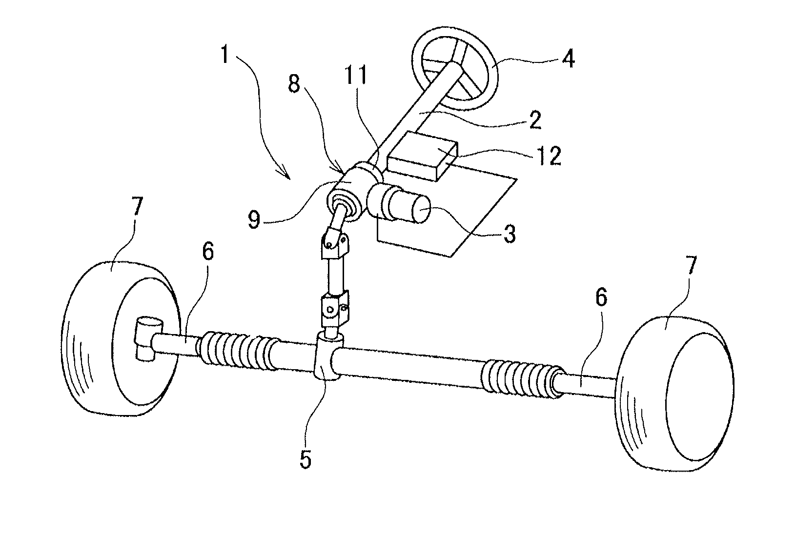
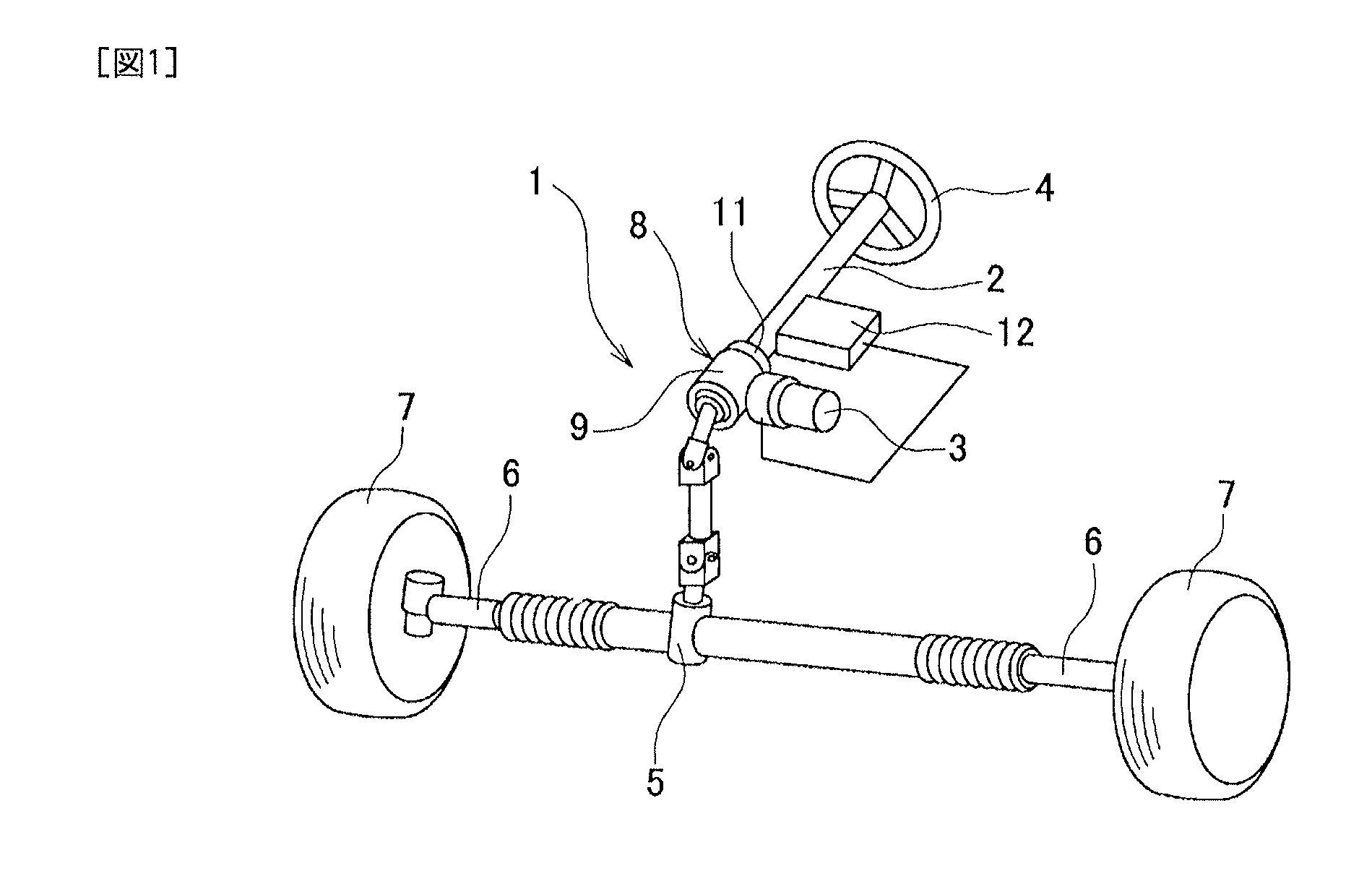
[0039]Hereinafter, an embodiment of the present invention will be described in detail based on the accompanying drawings. The object of the present embodiment is to provide a motor control method and device that can reduce torque ripples of a brushless motor without imposing a large calculation load on CPU. FIG. 1 is an explanatory diagram showing the configuration of EPS that uses a brushless motor; a control process of the present invention is carried out. An electric power steering device (EPS) 1 of FIG. 1 is of a column assist type that gives an operation assistance force to a steering shaft 2. In the EPS 1, the brushless motor 3 (which will be referred to as motor 3) is used as a power source.

[0040]To the steering shaft 2, a steering wheel 4 is attached. A steering force of the steering wheel 4 is transmitted to a tie rod 6 via a pinion and rack shaft that are disposed in a steering gear box 5 and are not shown in the diagram. To both ends of the tie rod 6, wheels 7 are connect...


PUM


Abstract

A control device 50 that drives and controls a brushless motor 3 of a four-pole 24-slot configuration includes: a base current calculation section 52 that calculates fundamental-wave current indicating a winding current value associated with maximum torque control; a correction component calculation section 59 that calculates 12th-order first higher harmonic wave component B sin 12(θ+β) to cancel a torque ripple of magnet torque, and 12th-order second higher harmonic wave component A sin 12(θ+α) to cancel a torque ripple of reluctance torque, based on a phase current value detected by a current sensor 64; a correction map 58 in which relation between phase current and parameters A, B, α, and β of the both higher harmonic wave components is stored; and a current correction section 60 that corrects supply current by superimposing each 12th-order higher harmonic wave component on the fundamental-wave current in order to create current command values Id′ and Iq′.

Description

TECHNICAL FIELD[0001]The present invention relates to a torque ripple reduction technique of a brushless motor, and particularly to a technique that is effective when being applied to a magnet assistance-type reluctance motor in which a magnet is embedded in a rotor and which rotates the rotor with the help of magnet torque caused by a magnetic force of the magnet as well as reluctance torque.BACKGROUND ART[0002]As an electric motor of a type that generates a rotational force by using a difference in magnetic resistance between a stator and a rotor, a reluctance motor has been known. In the reluctance motor, the rotor is rotated by reluctance torque caused by a difference in magnetic resistance. However, the reluctance torque is smaller than torque obtained from a magnet. Therefore, compared with a motor that uses a magnet and is the same in size, the reluctance motor tends to have a smaller output torque. In recent years, what has been proposed is a magnet assistance-type reluctanc...

Claims


Application Information

Patent Timeline
Patent Type & Authority Applications(United States)
IPC IPC(8): H02P6/10H02P6/00H02K1/27H02P21/00H02P6/28H02P21/05H02P21/22H02P23/04H02P27/04
CPCH02P6/10H02P6/002H02K1/2706B62D5/046H02K29/03H02P21/22H02P2207/05H02P21/00H02P27/04
Inventor OKUBO, MASAYUKIMITSUOKA, KEISUKE
Owner MITSUBA CORP
Why Eureka
Try Eureka