Motion detection solid-state image capturing device and motion detection system

a solid-state image and motion detection technology, applied in the field of motion detection solid-state image capture devices and motion detection systems, can solve the problems of increasing power consumption, inability to avoid cost increase, and large circuit scale, and achieve the effects of reducing random noise, improving motion detection sensitivity under low illumination, and reducing power consumption

Active Publication Date: 2015-11-05
SETECH CO LTD
View PDF0 Cites 18 Cited by
  • Summary
  • Abstract
  • Description
  • Claims
  • Application Information

AI Technical Summary

Problems solved by technology

The former Method 1 requires a frame memory, thereby resulting in a large circuit scale and increasing the power consumption.
Moreover, a cost increase cannot be avoided.
With the latter Method 2, a differential signal is generated at an edge portion of an object, thereby generating an erroneous detection signal, and resulting in a poor motion detection accuracy.
Particularly, when capturing a color video image, where one employs the Bayer arrangement, a typical color filter arrangement (2×2-pixel sets, in which G (green) color filters are arranged diagonally, with an R (red) and a B (blue) color finger arranged in the remaining positions), pixel signals of the same G color, which occur at least at every other pixels, will be used, thereby increasing the erroneous detection signal, thus further deteriorating the motion detection accuracy.

Method used


Image

  • Motion detection solid-state image capturing device and motion detection system
  • Motion detection solid-state image capturing device and motion detection system
  • Motion detection solid-state image capturing device and motion detection system

Examples


embodiment 1

of Motion Detection System

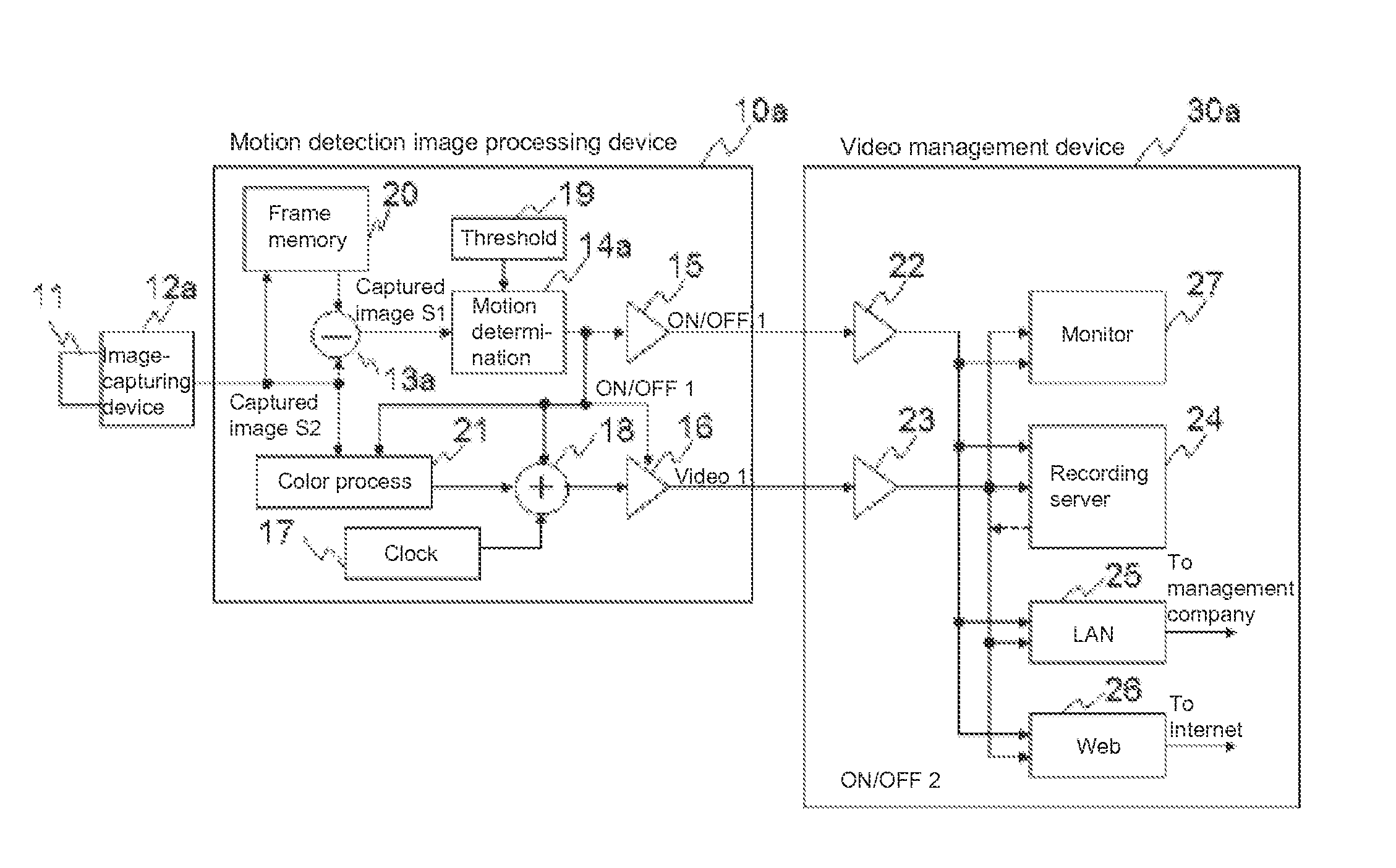
[0043]A motion detection system according to Embodiment 1 of the motion detection system of the present invention will be described in detail with reference to a block diagram of FIG. 1 showing a schematic configuration thereof.

[0044]The present motion detection system of Embodiment 1 includes a motion detection camera and a video management device 30a, wherein the motion detection camera is composed of an image-capturing device 12a including an image-capturing lens 11, and a motion detection image processing device 10a.

[0045]The motion detection image processing device 10a includes: a frame memory 20 for storing a captured image signal for one screen captured; a differential signal generation circuit 13a for generating a differential signal between a captured image (pixel) signal S1 and a captured image (pixel) signal S2 captured at different image-capturing times; a motion determination circuit 14a for determining the presence / absence of a moving object ...

embodiment 2

of Motion Detection System

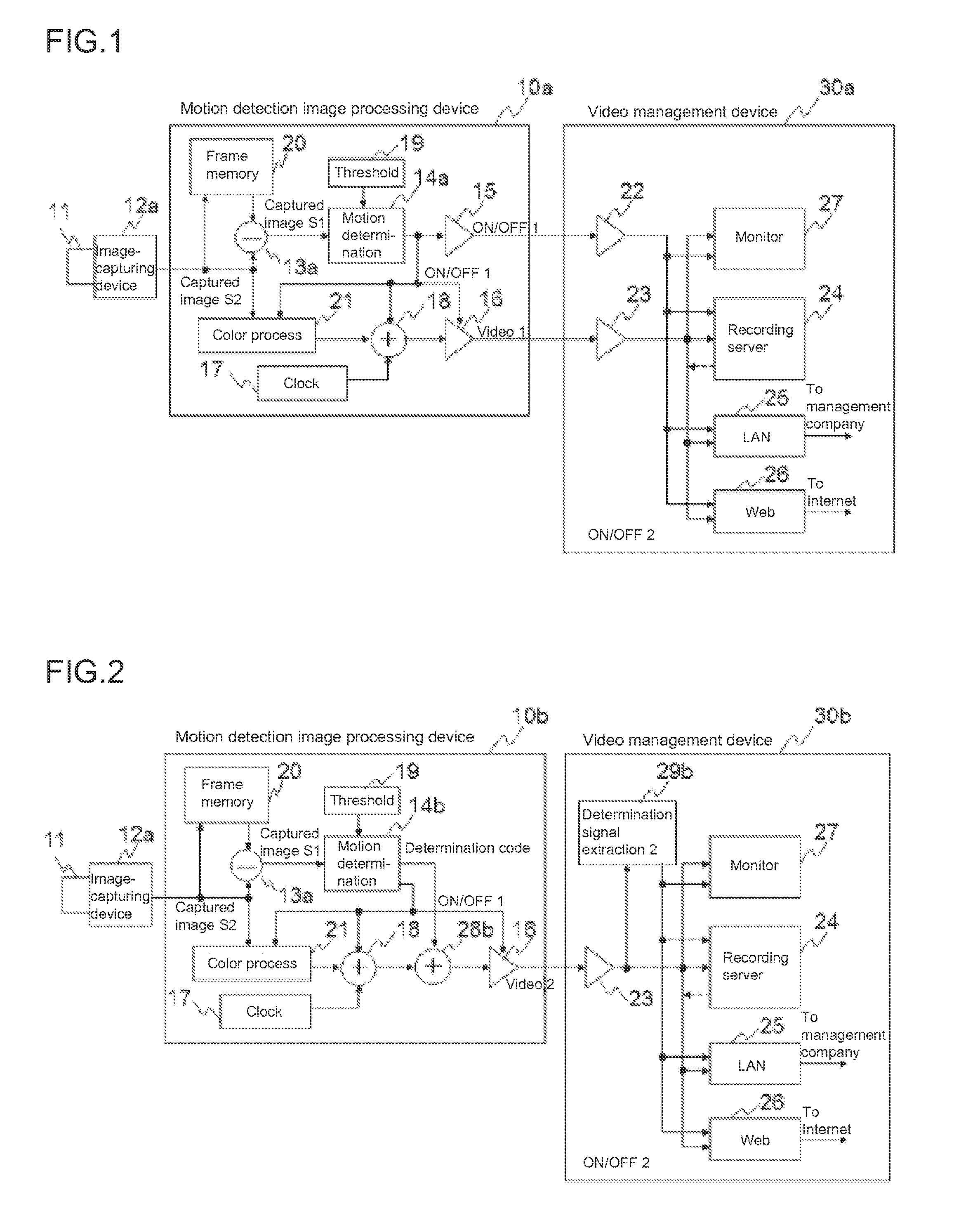
[0055]FIG. 2 is a block diagram showing a schematic configuration of a motion detection system according to Embodiment 2 of the motion detection system of the present invention. The present motion detection system of Embodiment 2 includes a motion detection camera and a video management device 30b, wherein the motion detection camera is composed of an image-capturing device 12a including an image-capturing lens 11, and a motion detection image processing device 10b. Configurations and operations that are different from those of Embodiment 1 will be described.

[0056]With the motion detection image processing device 10b, the motion determination signal output circuit 15 of FIG. 1 is eliminated so that the only output signal is video signal 2, thereby providing advantages such as allowing for use of a conventional transmission cable. A motion determination circuit 14b outputs a motion determination signal (ON / OFF1), and also outputs a determination code. As in ...

embodiment 3

of Motion Detection System

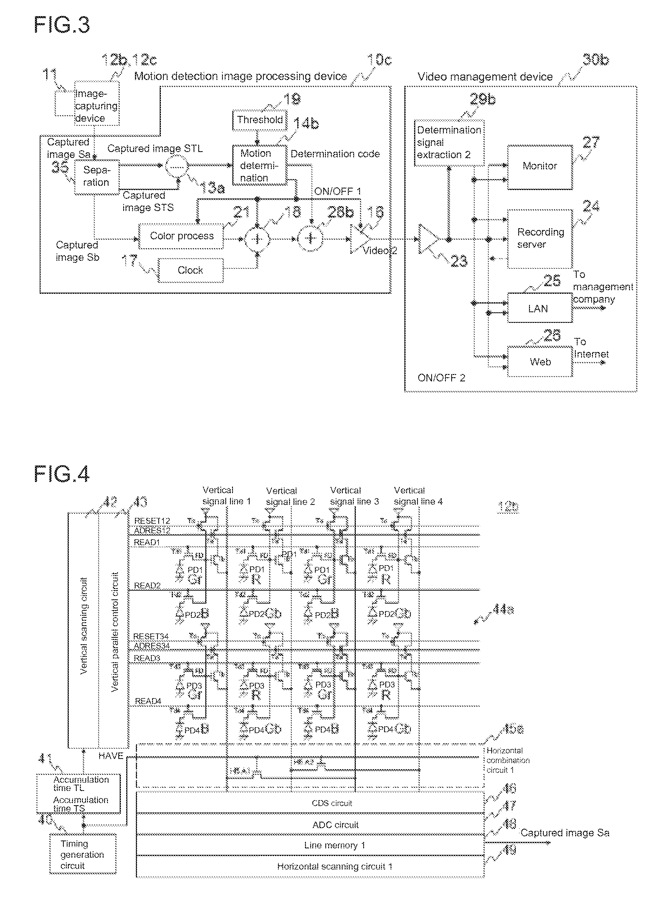
[0060]FIG. 3 is a block diagram showing a schematic configuration of a motion detection system according to Embodiment 3 of the present invention.

[0061]The present motion detection system of Embodiment 3 includes a motion detection camera and a video management device 30b, wherein the motion detection camera is composed of an image-capturing device 12b (12c) including an image-capturing lens 11, and a motion detection image processing device 10c. Configurations and operations that are different from those of Embodiment 2 will be described.

[0062]The motion detection image processing device 10c receives a captured image (pixel) signal for one screen captured by the image-capturing device 12b (12c), wherein the received signal is a captured image (pixel) signal Sa including a captured image (pixel) signal STL of which the accumulation time (over which the pixel area where photodiodes are arranged two-dimensionally is exposed) is long and a captured image (pixe...


PUM


Abstract

An object is to provide a motion detection solid-state image-capturing device and a motion detection system having a reduced power consumption and an improved motion detection accuracy. One solution is to combine together signals of a longer exposure time for a plurality of pixels and signals of a shorter exposure time for a plurality of pixels, which signals are output from a motion detection image-capturing device, and to determine the presence / absence of a moving object based on a differential signal between the signals of a longer exposure time and the signals of a shorter exposure time, wherein if it is determined that there is no moving object, at least part of a circuit of a motion detection image processing device or a video management device is stopped, thereby improving the detection accuracy and conserving the electric power.

Description

TECHNICAL FIELD[0001]The present invention relates to a motion detection solid-state image-capturing device and a motion detection system for detecting a motion of a video image on a captured image screen.BACKGROUND ART[0002]In the market of solid-state image-capturing devices, there has recently been a rapid increase in the sales of those of the CMOS sensor-type for use in mobile telephones. Each pixel section of a CMOS sensor-type solid-state image-capturing device includes a photoelectric conversion unit (hereinafter referred to as a pixel) for generating a signal charge according to the incident light, and an amplification unit for converting the signal charge of the photoelectric conversion unit into a signal voltage and amplifying the signal voltage.[0003]Solid-state image-capturing devices not only simply capture video images, but may also detect a motion of an object on a captured image screen of the solid-state image-capturing device. For example, they are used in motion de...

Claims


Application Information

Patent Timeline
Patent Type & Authority Applications(United States)
IPC IPC(8): H04N5/14H04N5/341H04N5/353G06T3/40H04N9/04H04N9/07G06T7/20H04N5/374H04N5/357
CPCH04N5/144H04N2209/045H04N5/341H04N5/353H04N5/357H04N9/045H04N9/07G06T7/20G06T3/4015G06T2207/10016G06T2207/10024G06T2207/10144G06T2207/20182G06T2210/61H04N2101/00G06T2200/32H04N5/374H04N23/6811H04N25/533H04N25/46H04N25/53H04N25/583H04N25/70H04N25/778H04N25/134H04N23/12H04N25/40H04N25/60H04N25/76
Inventor SEKINE, HIROKAZU
Owner SETECH CO LTD
Why Eureka
Try Eureka