
Plaque detection using a stream probe

a detection apparatus and stream probe technology, applied in the field of stream probes, can solve the problems of inconvenient detection of plaque detection apparatus, damage to the eye, and difficulty in identifying dental plaques by the naked eye, and achieve the effect of improving the detection of substances

Inactive Publication Date: 2015-11-12
KONINKLJIJKE PHILIPS NV
View PDF2 Cites 1 Cited by
  • Summary
  • Abstract
  • Description
  • Claims
  • Application Information

AI Technical Summary

Benefits of technology

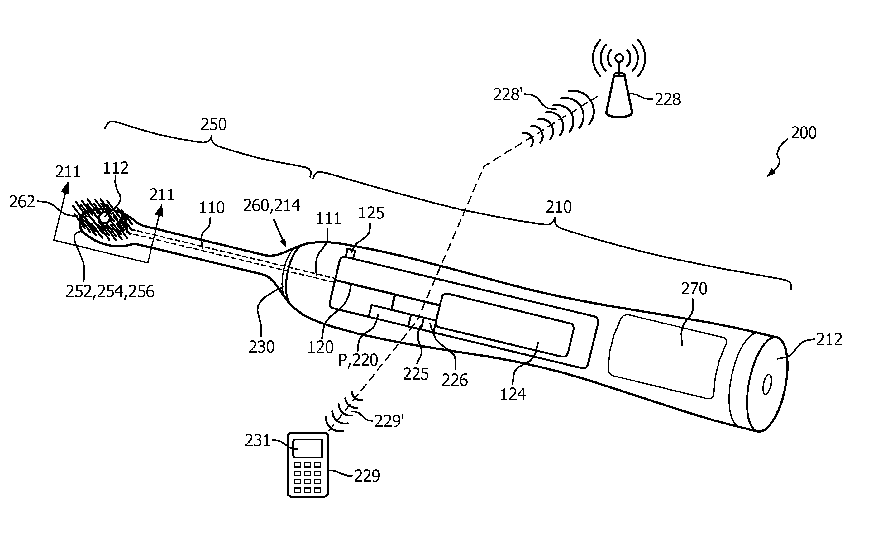
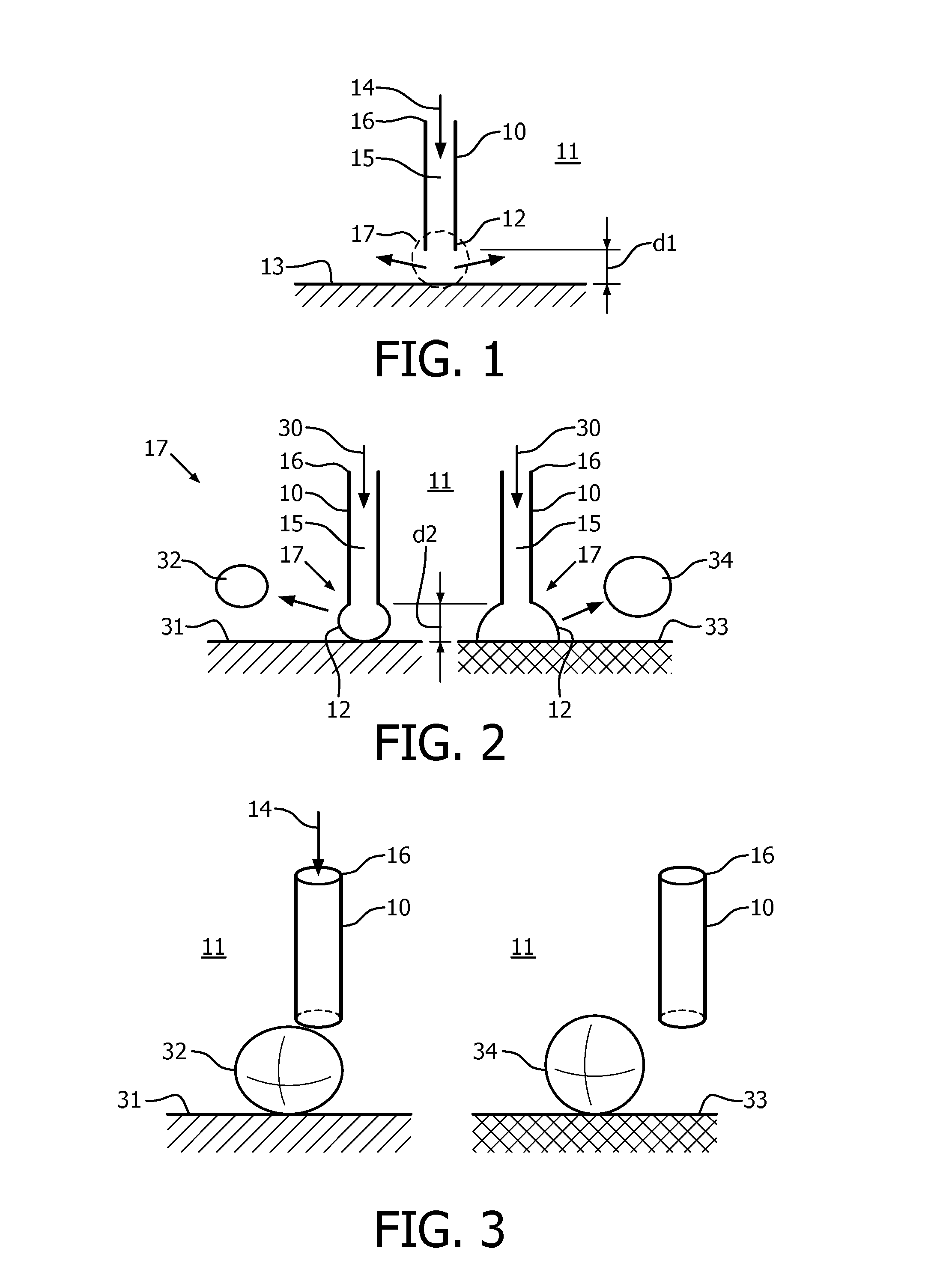
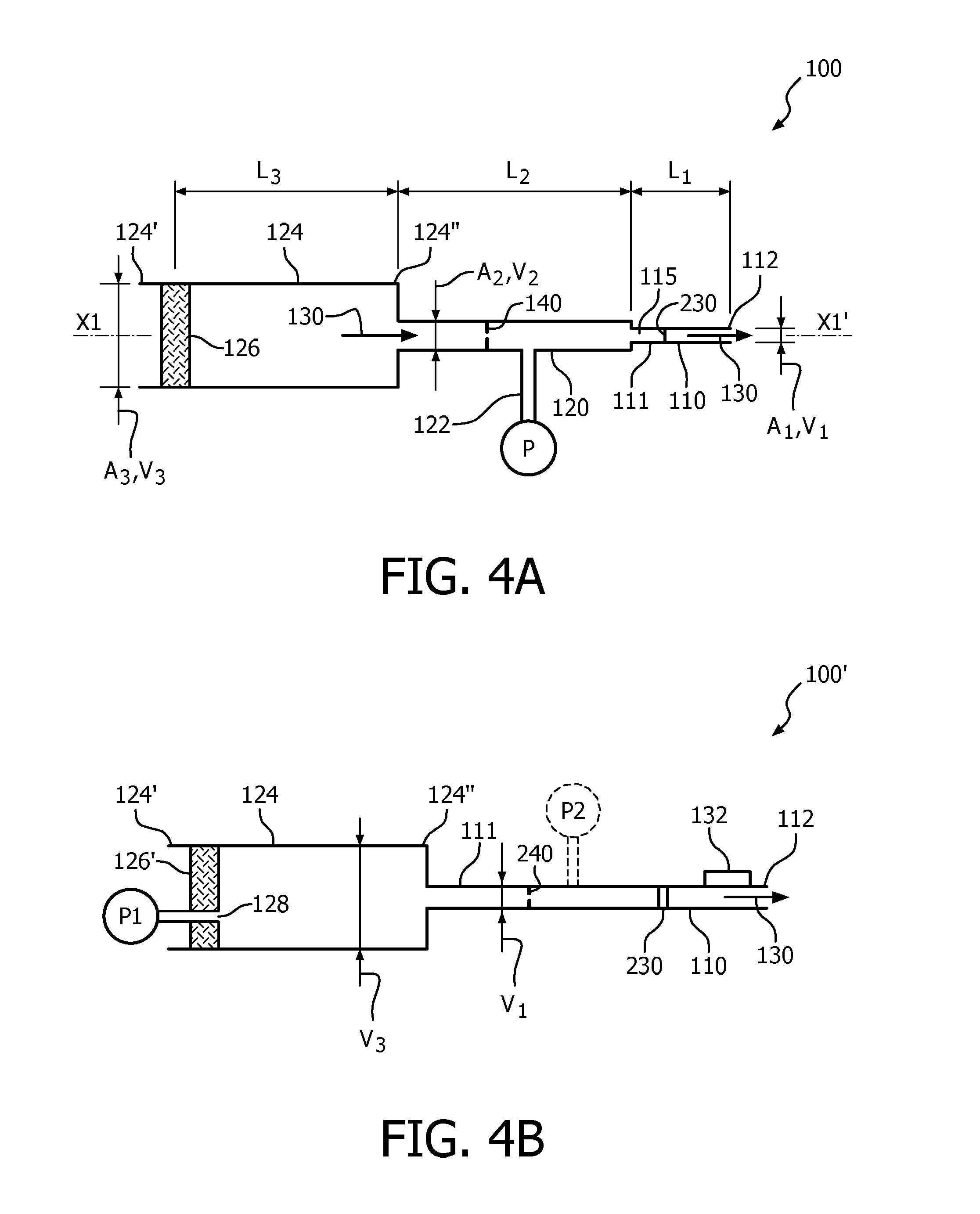
The present patent describes an apparatus for detecting the presence of a substance on a surface, particularly dental surfaces. The apparatus includes a proximal body portion and a distal probe portion that can be immersed in a fluid. The distal probe portion has an open port through which a second fluid can pass, enabling the detection of substances that may be present on the surface based on the measurement of signals correlating to the substances that obstruct the passage of fluid. The distal tip of the probe has a chamfered open port or a non-uniform wear profile to ensure accurate detection and plaque removal. The apparatus also includes two or more segments or components to improve performance and reliability.

Problems solved by technology

Dental plaques, however, are not easy to identify by the naked eye.
Specifically, it is known that each area of the eye absorbs different wavelengths of light and, if too much light is absorbed by the eye, the eye may be damaged.
The aforementioned devices, however, are not configured to automatically detect when the plaque detection apparatus are placed inside the mouth.
As a result thereof, potentially harmful radiation that could damage the eyes, or cause uncomfortable glare if exposed to the eyes, may result if proper handling precautions are not followed, e.g., consumer misuse.
Furthermore, this technique is especially suitable to detect old plaque; a distinction between teeth fluorescence and young (1 day old) plaque fluorescence is not made.

Method used


Image

  • Plaque detection using a stream probe
  • Plaque detection using a stream probe
  • Plaque detection using a stream probe

Examples


first embodiment

[0210]With reference to FIGS. 24A and 24B there are shown examples of probes 2400, 2402 having a castle-shape 2404 and a round shape 2406 distal tip (i.e., these shapes for the distal tips are structural configurations) to prevent false positive signals according to the present disclosure. Though these tip shapes are suitable to prevent false positives, a risk is that the signal level from the plaque layers reduces as well. Therefore, it is favorable to limit the dimension(s) of the open area. In one preferred embodiment, the height of the opening should be below 100 microns in order to achieve sufficiently large signals from plaque layers on the PMMA surface. Using the tip shape shown by FIG. 24B, and measuring the pressure versus distance to the PMMA surface, there is shown in FIG. 25 a clear improvement in pressure versus distance of the shaped tip probe 2400 with respect to the unshaped tip (negative values means no contact with the PMMA surface, zero means just in contact with ...

second embodiment

[0211]With reference to FIG. 26, according to the present disclosure, false positive signals are prevented by providing a structural configuration to a stream probe 2600 which includes small holes 2602 near the distal tip of the probe 2600 or at a proximal location from an open port 2604. The holes 2602 are preferably within 100 microns of the distal tip of the probe 2600. An advantage of this embodiment is that it results in a stronger probe tip, which can be beneficial in case of wear issues.

third embodiment

[0212]With reference to a cross-sectional view as shown by FIG. 27A, according to the present disclosure, the distal tip of a probe 2700 has a trumpet shape 2702 (i.e., structural configuration). That is, the inner diameter of the probe 2700 is larger at the end of the tube (at the distal tip) as compared to a position further away from the end. The tube appears to diverge at the distal tip. This shape prevents blocking of the distal tip of the probe 2700 by dental plaque or toothpaste.

[0213]In order to obtain large signals in case of a non-perpendicular tube orientation with respect to the tooth surface, it is beneficial to have a small tube diameter. Therefore, with respect to the embodiment shown by FIG. 27A, it is advantageous to apply a trumpet-like shape at the inside of the tube only, while the outside of the tube has a constant diameter throughout the length of the probe.

[0214]Another embodiment can be a tube having an inverse trumpet shape 2710 (i.e., structural configurati...


PUM

PropertyMeasurementUnit
inner diameteraaaaaaaaaa
diameteraaaaaaaaaa
frequencyaaaaaaaaaa

Abstract

An apparatus (100, 100′) is configured such that passage of a fluid (30) through an open port (136, 2604) of a distal probe tip (112, 112′) enables detection of a substance (116) that may be present on a surface (31, 33), e.g., a surface of a tooth, based on measurement of a signal correlating to a substance at least partially obstructing the passage of fluid (30) through the open port (136, 2604). The apparatus (100, 100′) includes a proximal pump portion (124) and at least one distal probe portion (110) configured to be immersed in another fluid (11), e.g., water in toothpaste foam. A corresponding system (3000) includes one or two such apparatuses (3100, 3200). A method of detecting the presence of a substance on a surface includes probing an interaction zone (17) for at least partial obstruction of flow of the fluid (30) through the distal probe tip (112, 112′). The distal probe tip (112, 112′) may have a structural configuration for preventing blocking of the open port (136, 2604). The distal probe tip (112, 112′) may also have a non-uniform wear profile. The at least one distal probe portion (110) may include two or multiple components to improve performance and reliability.

Description

TECHNICAL FIELD[0001]The present disclosure relates to apparatuses used for detecting the state of a surface. More particularly, the present disclosure relates to a stream probe that is utilized to detect the state of a dental surface.CROSS-REFERENCE TO RELATED APPLICATIONS[0002]This application claims the benefit of, and priority to, U.S. Provisional Patent Application No. 61 / 740,904 filed on Dec. 21, 2012 entitled “PLAQUE DETECTION USING A STREAM PROBE” and, U.S. Provisional Patent Application No. 61 / 746,361 filed on Dec. 27, 2012 entitled “PLAQUE DETECTION USING A STREAM PROBE;” the entire contents of both applications are incorporated herein by reference.BACKGROUND OF THE INVENTION[0003]Caries or periodontal diseases are thought to be infectious diseases caused by bacteria present in dental plaques. Removal of dental plaques is highly important for the health of oral cavities. Dental plaques, however, are not easy to identify by the naked eye. A variety of plaque detection appar...

Claims


Application Information

Patent Timeline
Patent Type & Authority Applications(United States)
IPC IPC(8): A61B5/00A61C17/22G01N7/00
CPCA61B5/4547G01N7/00A61B5/746A61B5/7405A61B5/742A61C17/227A61B5/6891A61B2562/0261A61B2562/0247A61C19/04A61C17/22A46B15/0002A61M5/1456A46B15/0036A61B5/0013A61M5/172A61B5/0088A61B5/4552A61B2562/0233A61B2576/02
Inventor SPRUIT, JOHANNES HENDRIKUS MARIAOUWELTJES, OKKEJOHNSON, MARK THOMASPRINS, MENNO WILLEM JOSEVAN GOOL, EDGAR MARTINUS
Owner KONINKLJIJKE PHILIPS NV
Learn More