Split Tip Catheter for Dialysis Treatment

a dialysis treatment and split-tip technology, applied in the field of medical devices, can solve the problems of difficult manufacturing, lumen leakage during use, delicate process of split-tip catheter, etc., and achieve the effect of convenient fabrication

Inactive Publication Date: 2015-11-12
VASCUTECH MEDICAL
View PDF2 Cites 5 Cited by
  • Summary
  • Abstract
  • Description
  • Claims
  • Application Information

AI Technical Summary

Benefits of technology

The present invention relates to a split tip catheter with an improved design to prevent kinking and facilitate efficient use. The invention has a lower durometer outer sleeve to prevent kinking in the arterial and venous lumens. Additionally, the catheter may be made from materials that are economical and durable.

Problems solved by technology

The splitting is a delicate process, however, and one that is difficult to achieve during manufacturing.
If a portion of one or both of the lumens is unintentionally cut during the splitting process, the lumens can leak during use.
During the molding process, however, excess stress is induced on the lumens adjacent to the hub.
In many cases, excess stress during the molding process also causes the lumens to leak during use.
Leaky lumens can be highly problematic and risky for patients.
For instance, leaky lumens cannot effectively filter harmful wastes, salt, and excess fluid from the patients' blood.

Method used


Image

  • Split Tip Catheter for Dialysis Treatment
  • Split Tip Catheter for Dialysis Treatment
  • Split Tip Catheter for Dialysis Treatment

Examples


Embodiment Construction

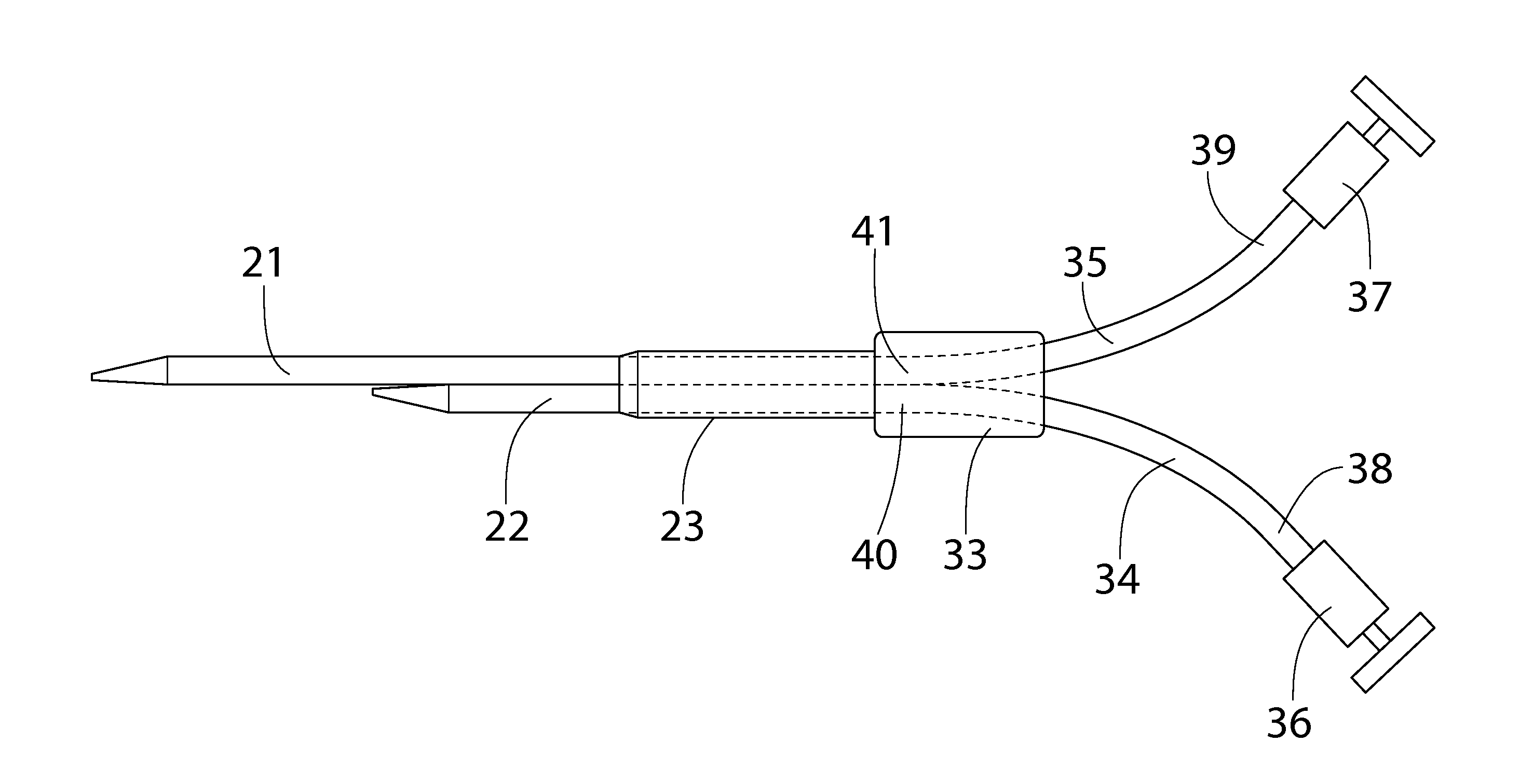
[0025]The present invention is directed towards a catheter that comprises a split tip. For purposes of clarity, and not by way of limitation, illustrative views of the present split tip catheter are described with references made to the above-identified figures. Various modifications obvious to one skilled in the art are deemed to be within the spirit and scope of the present invention.

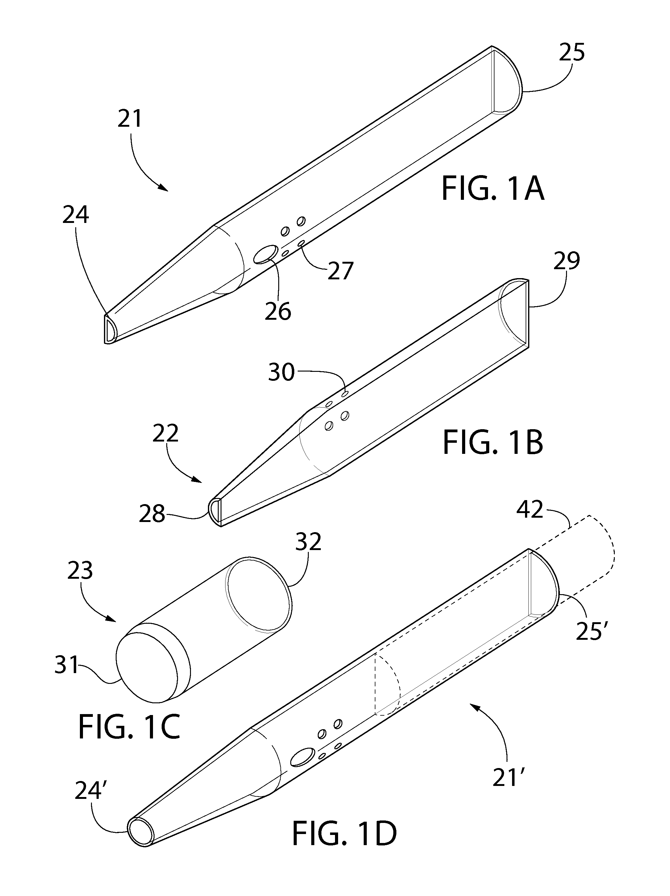
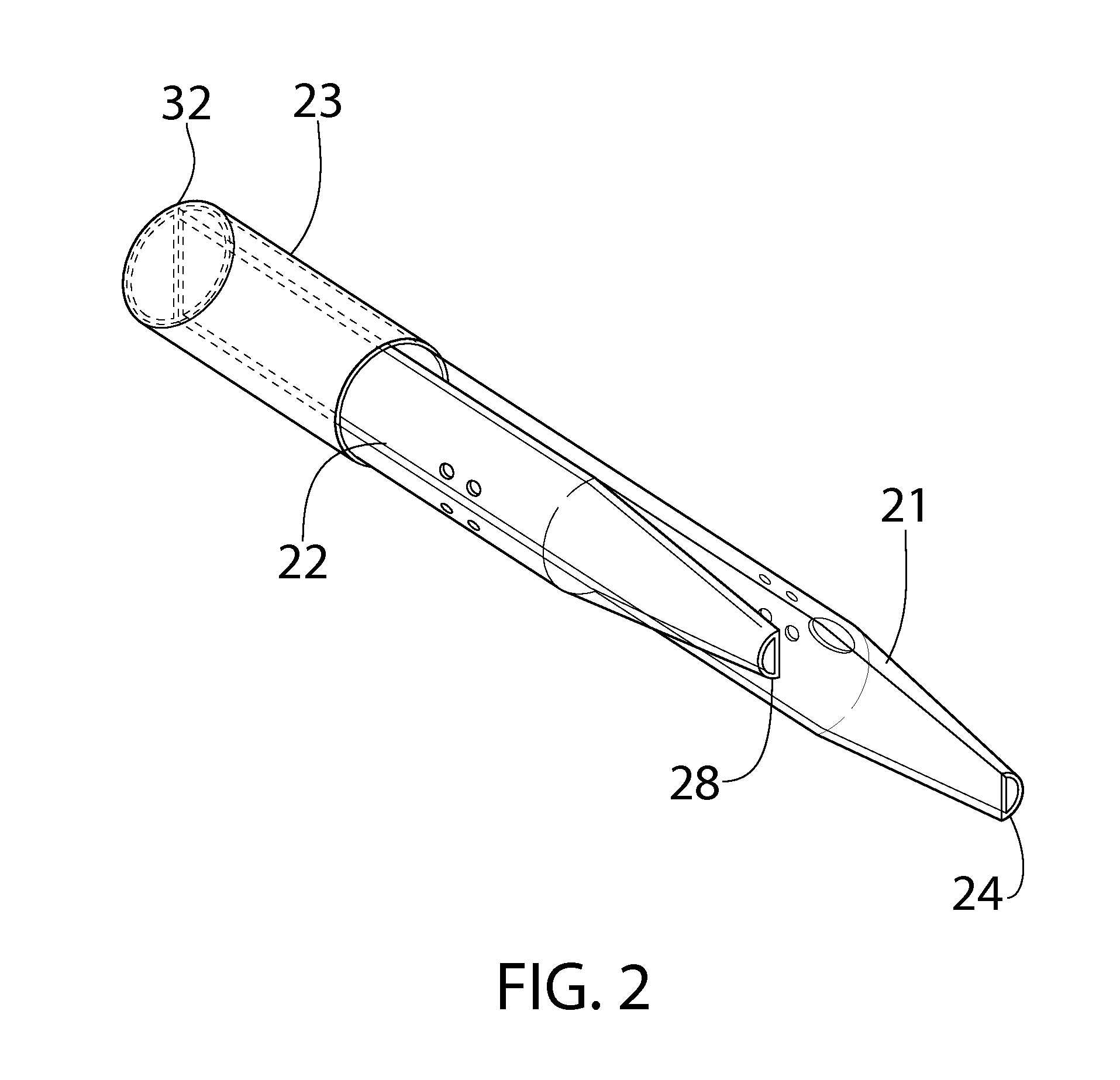
[0026]Referring now to FIG. 1A, there is shown a perspective view of a venous lumen of the present invention. The venous lumen 21 comprises an elongated tubular shape having a distal end 24 and a proximal end 25, wherein each of the distal end 24 and the proximal end 25 is open. The distance between the distal end 24 and the proximal end 25 defines a length of the venous lumen 21. The cross section of the venous lumen 21 is substantially D-shaped or semi-circular. In this regard, the venous lumen 21 comprises a curved side and a flat side.

[0027]The diameter of the cross section of the venous lumen 21 ...


PUM


Abstract

Disclosed is a split tip catheter having a tapered venous lumen and a tapered arterial lumen, wherein each of the lumens includes a D-shaped cross section. In one embodiment, the length of the venous lumen is greater than the length of the arterial lumen. The venous lumen and the arterial lumen are secured in a side-by-side configuration via an outer sleeve such that the proximal end of the outer sleeve is aligned with the proximal ends of the venous lumen and the arterial lumen, leaving the distal ends of the venous lumen and the arterial lumen free. The proximal ends of the outer sleeve, the venous lumen, and the arterial lumen are insert molded to a hub to connect the lumens to extensions such as venous and arterial blood lines for dialysis treatments.

Description

CROSS-REFERENCE TO RELATED APPLICATIONS[0001]This application claims the benefit of U.S. Provisional Patent Application No. 62 / 141,306, filed Apr. 1, 2015, which is hereby incorporated by reference in its entirety.FIELD OF THE INVENTION[0002]The present invention relates generally to the field of medical devices. More particularly, the present invention is directed to a split tip catheter for dialysis treatment.BACKGROUND OF THE INVENTION[0003]Split tip catheters are widely used for dialysis treatment. These catheters generally include a first lumen and a second lumen, wherein the two lumens are secured together in a side-by-side configuration. One known method of manufacturing two lumens in a side-by-side configuration is by extruding two integral lumens and then splitting a septum therebetween, allowing the lumens to separate. The splitting is a delicate process, however, and one that is difficult to achieve during manufacturing. If a portion of one or both of the lumens is uninte...

Claims


Application Information

Patent Timeline
Patent Type & Authority Applications(United States)
IPC IPC(8): A61M1/36A61M25/00
CPCA61M1/3661A61M25/003A61M25/0032A61M25/0028A61M2025/0031A61M25/0009A61M2025/0037A61M2025/0098A61M2202/0413A61M2202/0021A61M2207/00A61M2025/0034
Inventor NARDEO, MAHASE
Owner VASCUTECH MEDICAL
Why Eureka
Try Eureka