
Internal combustion engine using variable valve lift and skip fire control

a technology of internal combustion engine and valve lift, which is applied in the direction of electric control, machines/engines, mechanical equipment, etc., can solve the problems of limited control range of cam phasers, complex control algorithms, and high hardware requirements for valve lift control

Active Publication Date: 2015-11-12
TULA TECH INC
View PDF67 Cites 38 Cited by
  • Summary
  • Abstract
  • Description
  • Claims
  • Application Information

AI Technical Summary

Benefits of technology

The patent text describes a method and system for controlling an internal combustion engine with multiple cylinders. Specifically, the method involves deactivating one cylinder and controlling another cylinder using variable valve lift to control the amount of air in the cylinder, which improves engine performance. The system includes an internal combustion engine with multiple cylinders arranged in a bank, where at least one cylinder can be deactivated and at least one cylinder can have variable valve lift control. Overall, this technology allows for improved engine performance and efficiency.

Problems solved by technology

A disadvantage of valve lift control is that the hardware needed to implement valve lift control tends to be relatively expensive and the control algorithms complex.
Other techniques (e.g. altering the valve timing with a cam phaser) can also be used to adjust the MAC; however, use of a cam phaser has only a limited range of control over the MAC.
There are a number of other engine parameters, including fuel charge, spark advance timing, etc. that may be used to alter the torque provided by each firing as well; however, use of these control parameters generally results in a lower fuel economy.
When a cylinder is “deactivated”, its piston typically still reciprocates; however, neither air nor fuel is delivered to the cylinder so the piston does not deliver any net power.
However, limiting skip fire operation to a limited set of available firing patterns / fractions while operating the engine in an optimal manner may result in providing a mismatch between the output torque and the requested input torque command.
Although these methods can provide a matched torque output to input torque command, they come at the expense of increased pumping losses.

Method used


Image

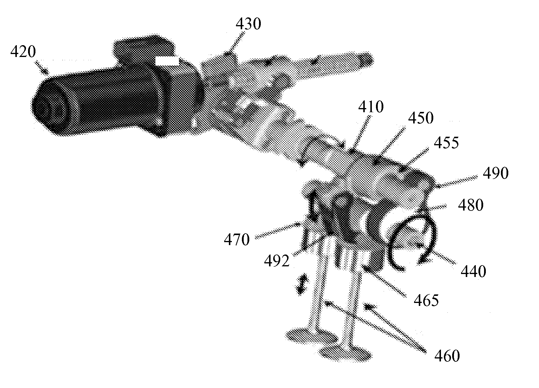
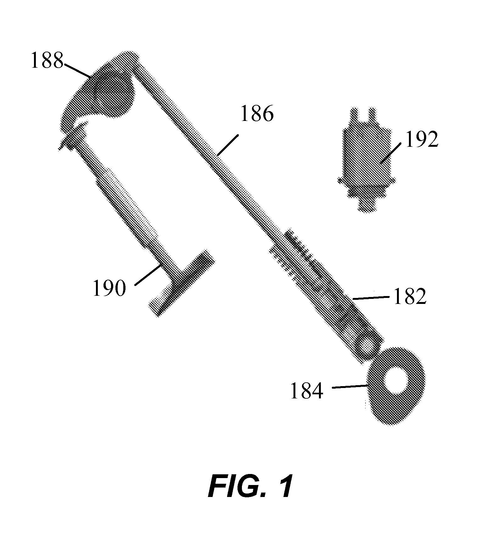
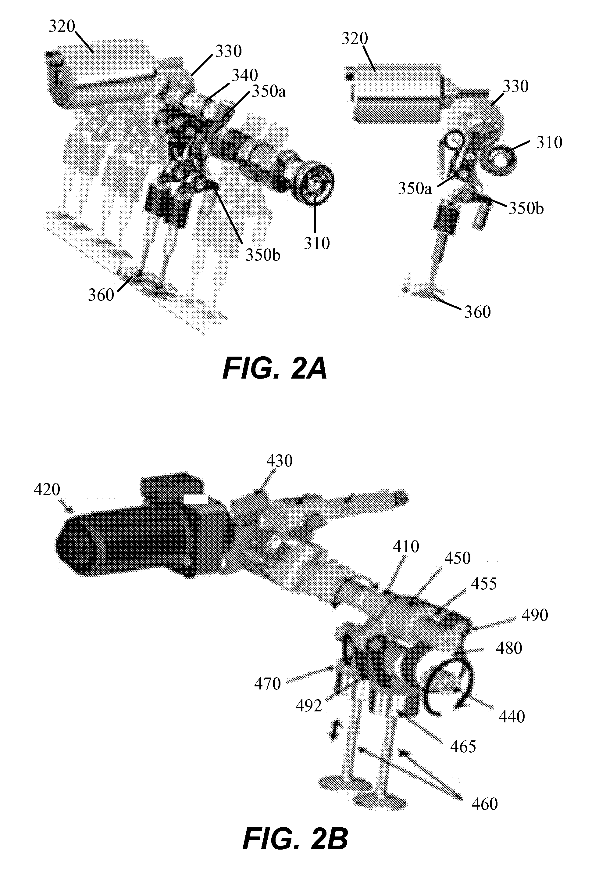
  • Internal combustion engine using variable valve lift and skip fire control
  • Internal combustion engine using variable valve lift and skip fire control
  • Internal combustion engine using variable valve lift and skip fire control

Examples


Embodiment Construction

[0003]The described embodiments relate generally to internal combustion engines and to methods and arrangements for controlling internal combustion engines to operate more efficiently. More particularly, methods and arrangements for controlling internal combustion engines using variable valve lift and cylinder deactivation are described.

[0004]2. Description of the Related Art

[0005]The output of many internal combustion engines is controlled by adjusting the mass air charge (MAC) delivered to each fired cylinder. An engine control unit (ECU) directs delivery of the appropriate fuel charge for the commanded MAC. Gasoline fueled engines generally operate with an air / fuel ratio at or near stoichiometry to facilitate conversion of harmful pollutants to more benign compounds in a catalytic converter. Control of the MAC is most easily accomplished by adjusting the throttle position which in turn alters the intake manifold pressure (MAP). However, it should be appreciated that the MAC can b...


PUM


Abstract

An internal combustion engine capable of cylinder deactivation or skip fire control in combination with variable valve lift control. One bank of cylinders can be deactivated while the air induction of the other bank of cylinders is regulated using variable valve lift control to increase engine efficiency. An internal combustion engine with two cylinder banks, where control of one cylinder bank using skip fire control can be operating at an appropriate firing fraction in combination with variable valve lift control on the other cylinder bank. A single bank of cylinders can be controlled in a skip fire manner in conjunction with variable valve lift control.

Description

CROSS REFERENCE TO RELATED APPLICATIONS[0001]This application claims the benefit of U.S. Provisional Patent Application Nos. 61 / 991,767, filed May 12, 2014 and entitled “INTERNAL COMBUSTION ENGINE USING VARIABLE VALVE LIFT AND SKIP FIRE CONTROL”. The foregoing application is hereby incorporated herein by reference.BACKGROUND[0002]1. Field of the Described Embodiments[0003]The described embodiments relate generally to internal combustion engines and to methods and arrangements for controlling internal combustion engines to operate more efficiently. More particularly, methods and arrangements for controlling internal combustion engines using variable valve lift and cylinder deactivation are described.[0004]2. Description of the Related Art[0005]The output of many internal combustion engines is controlled by adjusting the mass air charge (MAC) delivered to each fired cylinder. An engine control unit (ECU) directs delivery of the appropriate fuel charge for the commanded MAC. Gasoline f...

Claims


Application Information

Patent Timeline
Patent Type & Authority Applications(United States)
IPC IPC(8): F02D17/02F01L1/344F02D41/00
CPCF02D17/02F01L1/344F02D41/0085F01L1/146F01L1/181F01L1/34F01L13/0005F01L13/0026F01L2013/001F01L2013/0068F01L2013/0073F01L2305/00F01L2800/08F01L2820/01F02D41/0002F02D41/0082F02D41/0087F02D2041/0012Y02T10/40
Inventor SHOST, MARK A.YOUNKINS, MATTHEW A.
Owner TULA TECH INC
Learn More