
Sensor calibration method and apparatus

a technology of sensor calibration and calibration solution, applied in the direction of gas analyser calibration, instrumentation, diagnostic recording/measuring, etc., can solve the problems of unsatisfactory containers, affecting the concentration of analytes of interest in the calibration solution, and not being able to meet the requirements of calibration

Inactive Publication Date: 2015-11-12
SPHERE MEDICAL
View PDF7 Cites 11 Cited by
  • Summary
  • Abstract
  • Description
  • Claims
  • Application Information

AI Technical Summary

Benefits of technology

The present invention aims to offer a method for calibrating an apparatus with a sensor that can detect substances of interest in a sample. The invention aims to reduce the use of cumbersome calibration solution packaging and provide accurate calibration without the need for multiple calibration steps.

Problems solved by technology

Although the concept of calibration is straightforward enough, its practical implementation is not without problems.
During transit or storage, the packaged calibration solutions are typically exposed to varying environmental conditions such as temperature and pressure, which can affect the concentrations of analytes of interest in the calibration solution.
This is particularly problematic for calibration solutions into which gases such as O2 and / or CO2 are dissolved because the concentration of a dissolved gas is highly sensitive to such environmental variations.
Such problems can for instance occur if the calibration solution is packaged in a gas-permeable container or in a container with a headspace, which allows for the gas concentrations in the calibration solution to change freely upon such changes in the environmental conditions.
However, such containers are not ideal from the perspective of the end user especially if they have to be used frequently; they are cumbersome to open with the risk of glass particles generated during the breaking of the glass vial finding their way into the apparatus, which is entirely unacceptable if the apparatus is connected to a patient.
Also, such packaging can be quite costly compared to less robust packaging materials such as polymer-based syringes, which is also undesirable to the end user from an economic perspective.

Method used


Image

  • Sensor calibration method and apparatus
  • Sensor calibration method and apparatus
  • Sensor calibration method and apparatus

Examples


Embodiment Construction

[0028]Embodiments of the invention are described in more detail and by way of non-limiting examples with reference to the accompanying drawings, wherein:

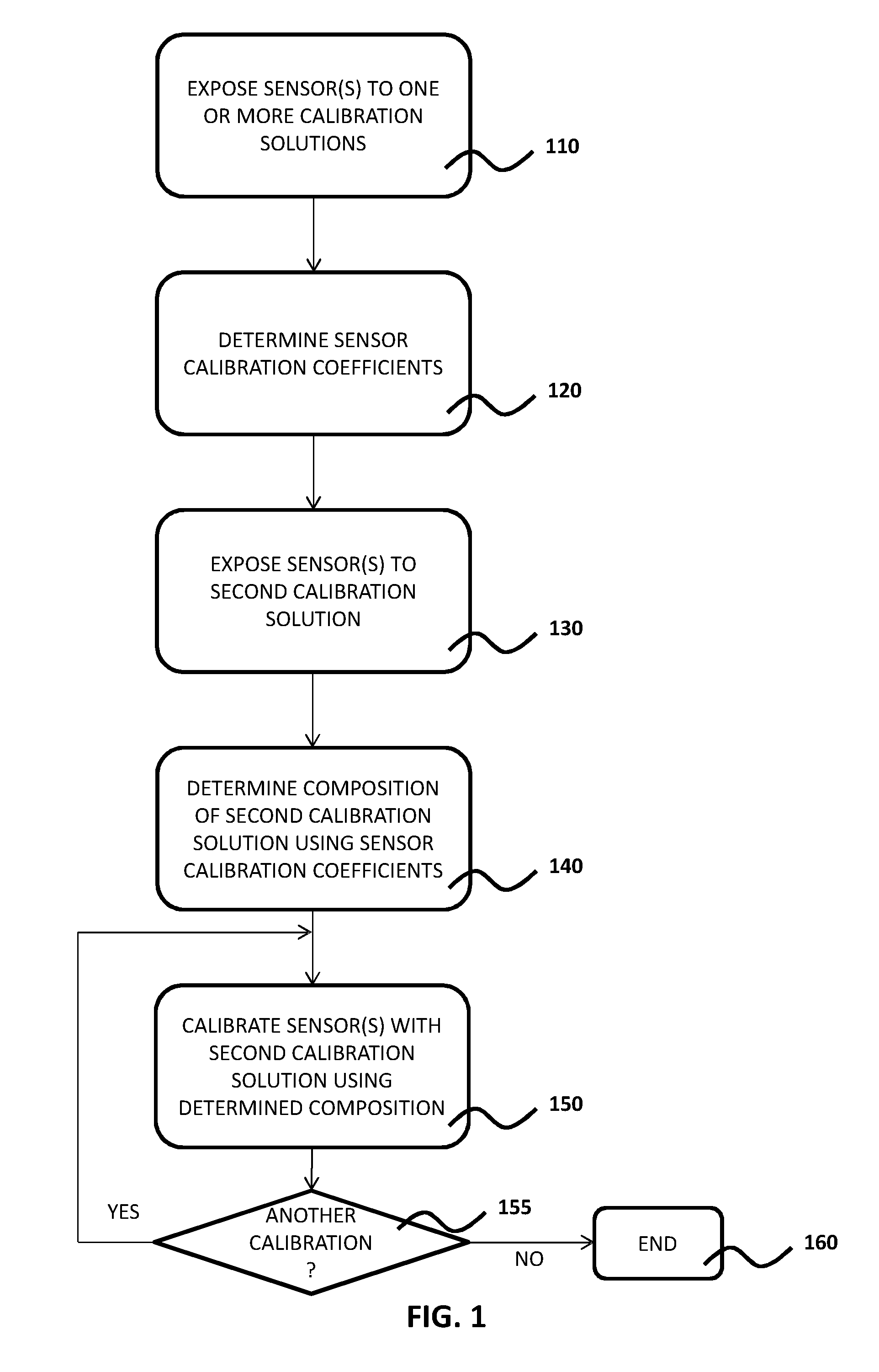
[0029]FIG. 1 depicts a flow chart of an example embodiment of the method of the present invention;

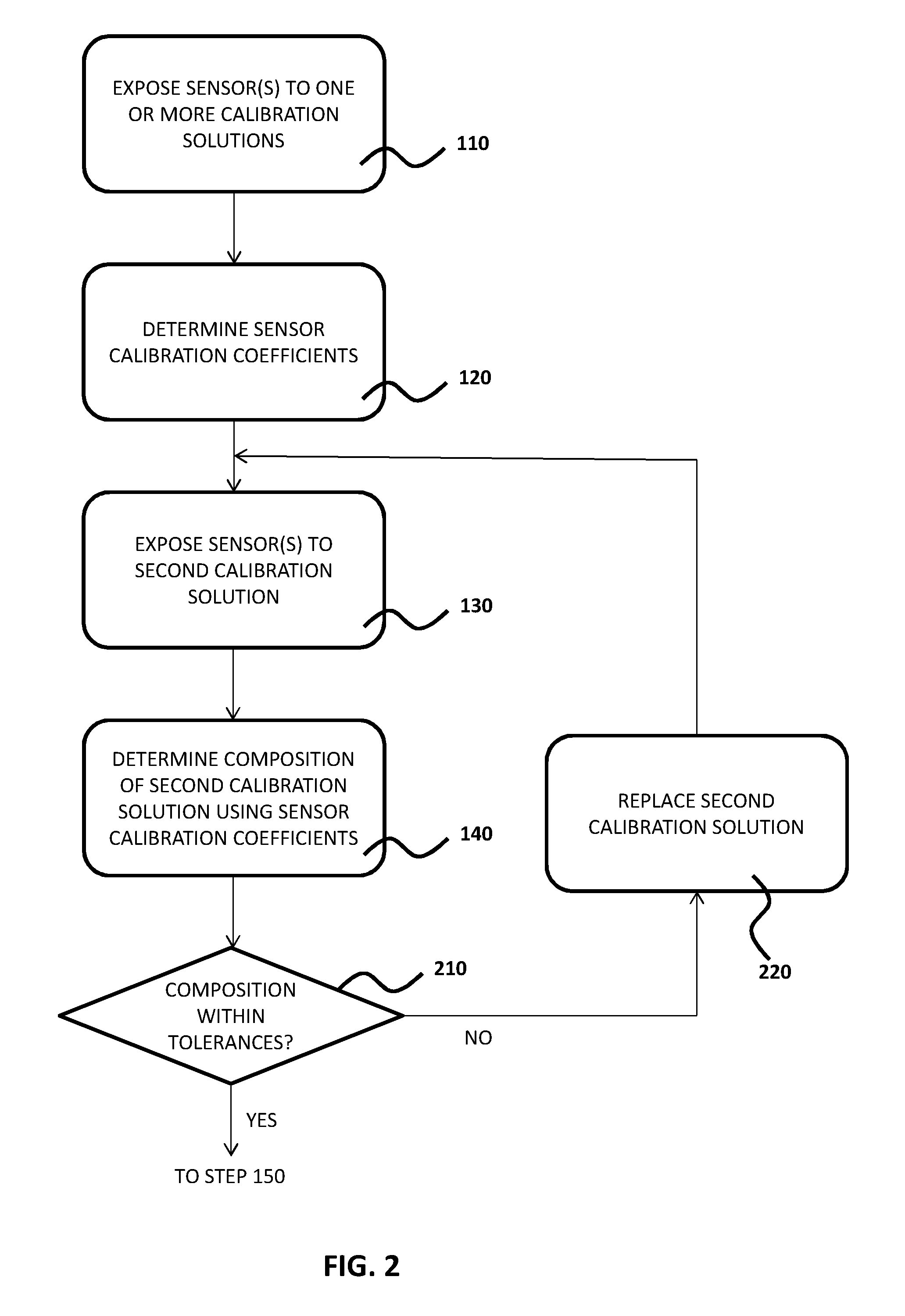
[0030]FIG. 2 depicts a flow chart of an aspect of another example embodiment of the method of the present invention;

[0031]FIG. 3 depicts a flow chart of an aspect of yet another example embodiment of the method of the present invention; and

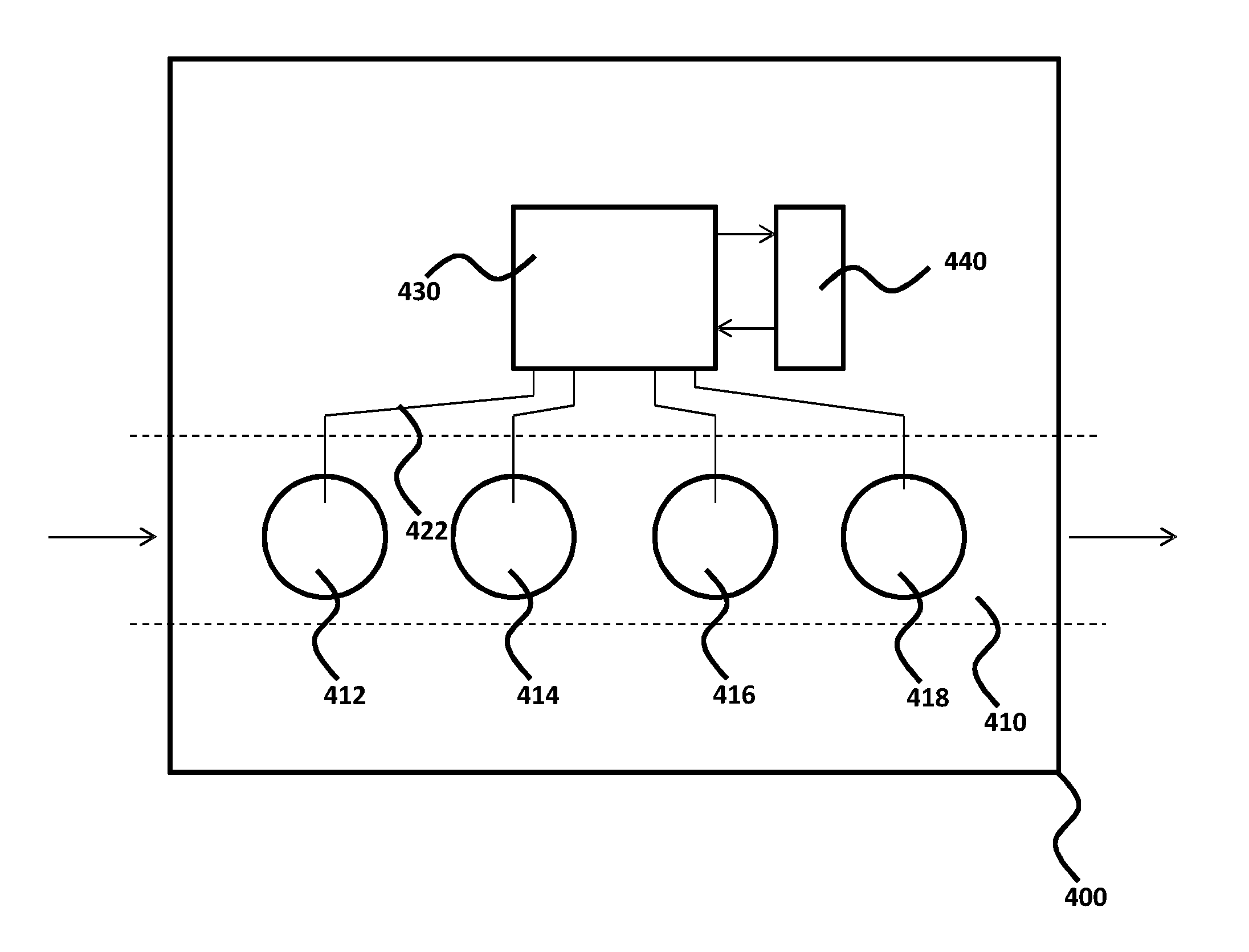
[0032]FIG. 4 schematically depicts an example embodiment of the apparatus of the present invention.

DETAILED DESCRIPTION OF THE DRAWINGS

[0033]It should be understood that the Figures are merely schematic and are not drawn to scale. It should also be understood that the same reference numerals are used throughout the Figures to indicate the same or similar parts.

[0034]FIG. 1 depicts a flow chart of a non-limiting example embodiment of the method of the present invention, which will be explained with the...


PUM

PropertyMeasurementUnit
compositionaaaaaaaaaa
compositionsaaaaaaaaaa
calibration frequencyaaaaaaaaaa

Abstract

Disclosed is a method of calibrating an apparatus comprising at least one sensor for detecting one or more analytes of interest in a sample, the method comprising measuring a first set of responses of the at least one sensor to at least one first calibration solution having a known composition of the one or more analytes of interest; measuring a second response of the at least one sensor to a second calibration solution having an approximately known composition of the one or more analytes of interest; determining the composition of the second calibration solution from the difference between the first set of responses and the second response; and periodically calibrating the at least one sensor with the second calibration solution using said determined composition. An apparatus and computer program product for executing this method are also disclosed.

Description

FIELD OF THE INVENTION[0001]The present invention relates to a method of calibrating an apparatus comprising at least one sensor for detecting one or more analytes of interest in a sample.[0002]The present invention further relates to an apparatus comprising a processor, a memory operatively coupled to the processor and at least one sensor for detecting one or more analytes of interest in a sample operatively coupled to the processor.BACKGROUND OF THE INVENTION[0003]In order to obtain an accurate reading of the presence of one or more analytes of interest in a sample using an apparatus comprising one or more sensors for detecting one of the analytes of interest, it is necessary to (periodically) calibrate the one or more sensors with one or more calibration solutions having known concentrations of the one or more analytes of interest. The response of the one or more sensors to the calibration solution(s) is measured and calibration coefficients for each sensor are derived from the s...

Claims


Application Information

Patent Timeline
Patent Type & Authority Applications(United States)
IPC IPC(8): G01N33/00G01N33/48
CPCG01N33/48G01N33/0006A61B5/1495G01N33/492G01N27/4163
Inventor HENDRY, STUARTTROUGHTON, GAVIN
Owner SPHERE MEDICAL
Learn More