
Electronic latch of a motor-vehicle closure device, provided with an improved backup energy source

a technology of motor vehicles and latches, applied in the field of electronic latches, can solve the problems of increased area occupation, weight and additional costs, redundancy of mechanical mechanisms,

Active Publication Date: 2015-11-19
MAGNA CLOSURES INC
View PDF4 Cites 59 Cited by
  • Summary
  • Abstract
  • Description
  • Claims
  • Application Information

AI Technical Summary

Benefits of technology

The present invention provides an electronic latch with a backup power source, which solves the issue of power loss during power failures.

Problems solved by technology

As it is known, a common problem related to electrical latches is that of controlling, as it is also required by security regulations, opening and closing of the doors even in case of failure of the main power supply of the vehicle, or in case of interruptions or breaking of the electrical connection between the main power supply and the electric motor in the latch; this kind of situation may occur for example in case of an accident or crash involving the vehicle.
However, the presence of a redundant mechanical mechanism entails higher area occupation and weight and additional costs, and also represents a further constriction for designing the door.
However, designing of a backup power source, and of the related electronic circuitry, for the electric latch assembly has proven to be a difficult task, for example due to size requirements, as also has proven to be difficult meeting desired electrical performance, for example in terms of energy density or current output, especially in automotive operating conditions.
The capacitor group includes a vast number of capacitors, of the high voltage type (withstanding up to V), series or parallel connected, thus requiring a relevant amount of space on the circuit board; moreover, such solution generally needs a further backup energy source, since the supercapacitor group may only be able to supply power for a limited amount of time.
In other words, the capacitor group may not be able to guarantee a sufficient and autonomous backup energy source for the vehicle latch.

Method used


Image

  • Electronic latch of a motor-vehicle closure device, provided with an improved backup energy source
  • Electronic latch of a motor-vehicle closure device, provided with an improved backup energy source
  • Electronic latch of a motor-vehicle closure device, provided with an improved backup energy source

Examples


Embodiment Construction

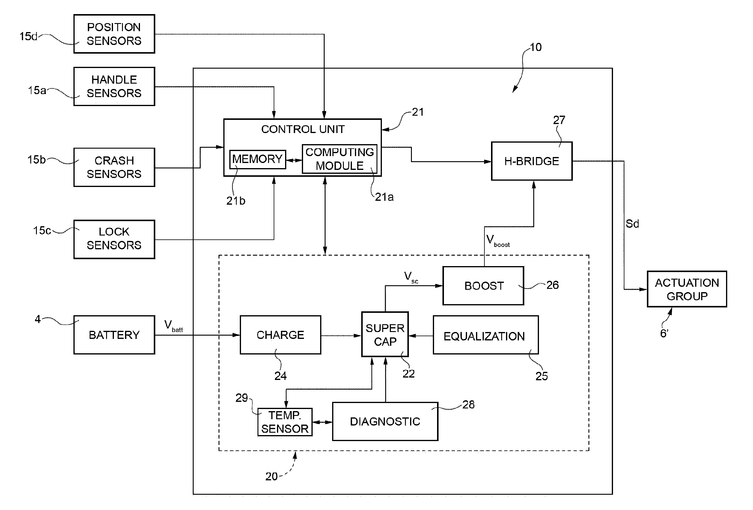
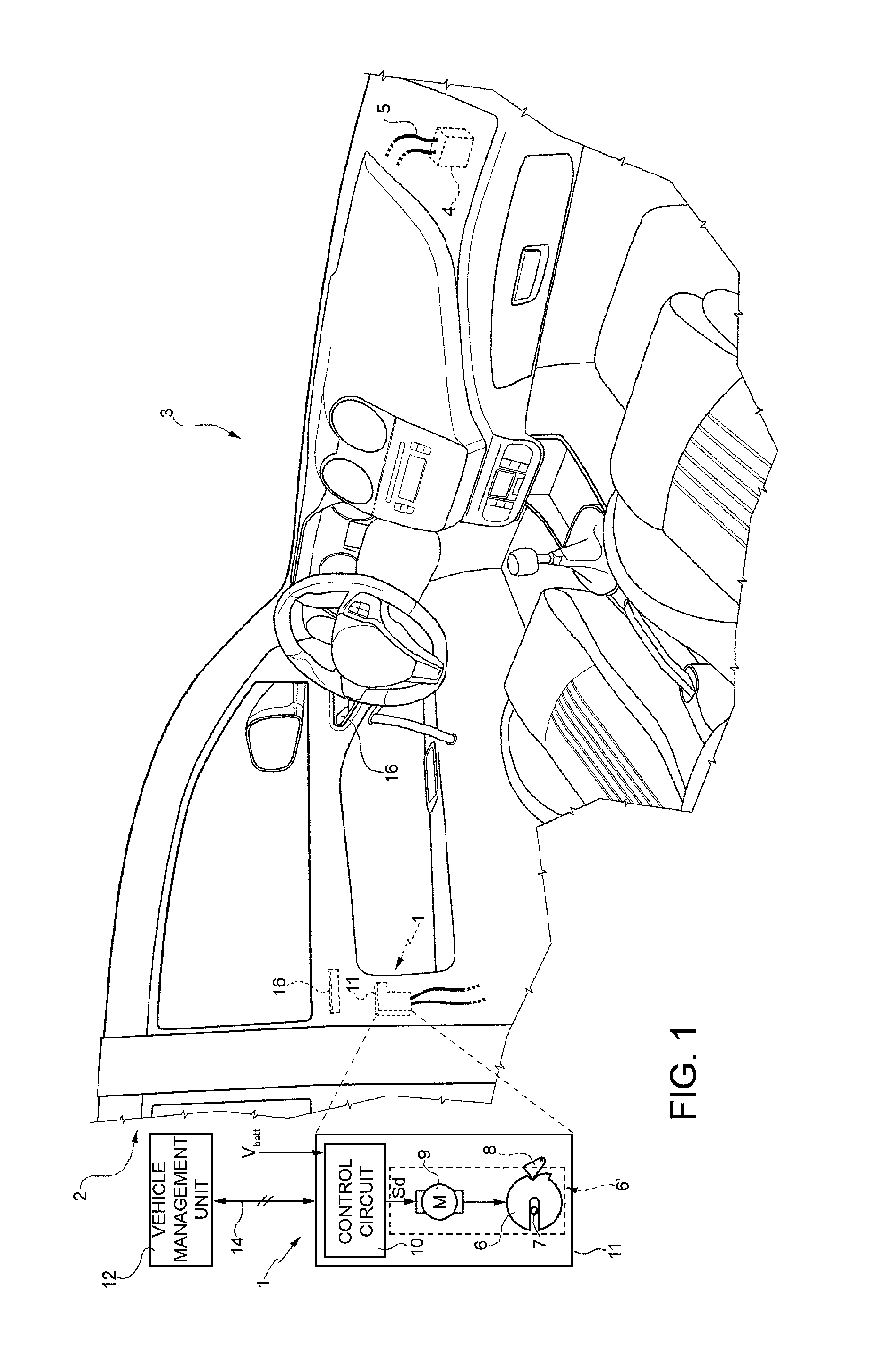
[0025]Number 1 in FIG. 1 indicates as a whole an electronic latch assembly (hereinafter e-latch assembly 1), coupled to a side door 2 of a motor vehicle 3 (however, it is again underlined that the e-latch assembly 1 may equally be coupled to any kind of closure device of the motor vehicle 3).

[0026]The e-latch assembly 1 is electrically connected to a main power source 4 of the motor vehicle 3, for example a main battery providing a battery voltage Vbatt of 12 V, through an electrical connection element 5, for example a power cable (the main power source 4 may equally include a different source of electrical energy within the motor vehicle 3, for example an alternator).

[0027]The e-latch assembly 1 includes an actuation group 6′, including an electric motor, operable to control actuation of the door 2 (or in general of the vehicle closure device).

[0028]In a possible embodiment, the actuation group 6′ includes a ratchet 6, which is selectively rotatable to engage a striker 7 (fixed to ...


PUM


Abstract

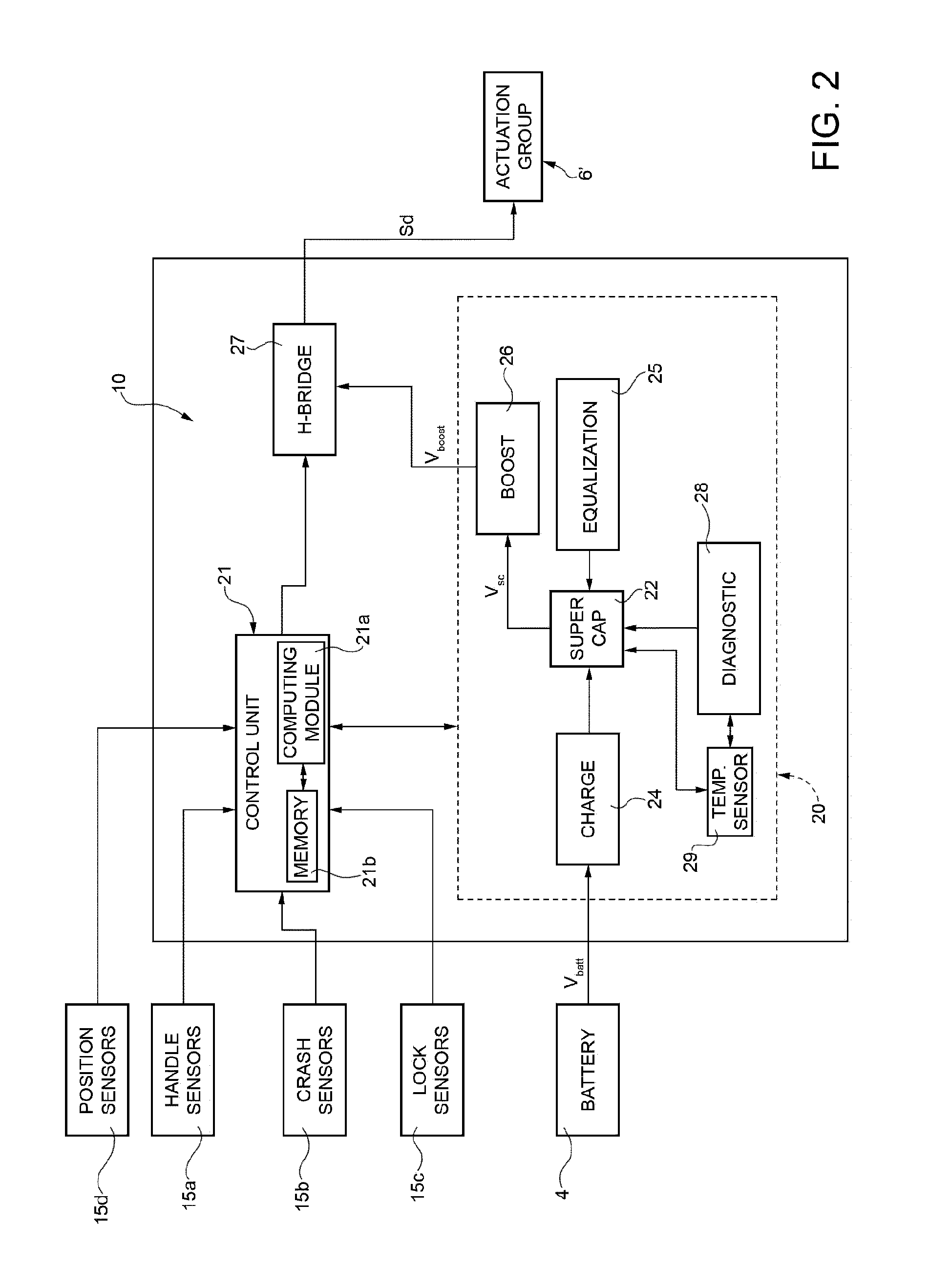
An electronic latch assembly for a closure device of a motor vehicle, having an actuator group operable to control actuation of the closure device and an electric motor controllable to drive the actuator group and supplied, during a normal operating condition, by a main power source of the motor vehicle providing a main supply voltage (Vbatt); the electronic latch assembly has a backup energy source, and a control unit controlling the backup energy source to supply the electric motor during a failure operating condition. The backup energy source has a supercapacitor group, which stores energy during the normal operating condition and provides a backup supply voltage (Vsc) to supply the electric motor (9) during the failure operating condition.

Description

TECHNICAL FIELD[0001]The present invention relates to an electronic latch (commonly known as e-latch) of a motor-vehicle closure device, provided with an improved backup energy source.BACKGROUND ART[0002]This application claims priority to and the benefit of the filing dates of IT Patent Application No. TO2012A001143, IT Patent Application No. TO2012A001144, and IT Patent Application No. TO2012A001145 filed on Dec. 24, 2012 and U.S. Patent Application No. 61 / 748,262, U.S. Patent Application No. 61 / 748,274, and U.S. Patent Application No. 61 / 748,286 filed on Jan. 2, 2013, and references and incorporates by reference herein the entirety of the content of each such application.[0003]In the following description and the accompanying claims, the expression “closure device” will be used to generally indicate any element movable between an open position and a closed position, respectively opening and closing an access to an inner compartment of a motor vehicle, therefore including, boot, r...

Claims


Application Information

Patent Timeline
IPC IPC(8): E05B81/86H02J7/00
CPCE05B81/86H02J7/345H02J7/0052B60L58/21B60L58/25B60L58/15Y02T10/70H02J2207/50H02J9/061E05B77/12E05B81/14H02J7/00
Inventor DENTE, DAVIDE
Owner MAGNA CLOSURES INC
Learn More