System having a fuel distributor and multiple fuel injectors

a fuel distributor and injector technology, applied in the field of systems, can solve the problems of high number and complexity of mounting elements, and the work involved in the initial assembly during the manufacture, and also in the deinstallation and reinstallation in a service situation is considerable. , to achieve the effect of cost-effectiveness, increased loading capacity and high operating pressur

Active Publication Date: 2015-11-19
ROBERT BOSCH GMBH
View PDF12 Cites 25 Cited by
  • Summary
  • Abstract
  • Description
  • Claims
  • Application Information

AI Technical Summary

Benefits of technology

[0012]It is also advantageous that a contact surface is developed on the first leg of the holding element, at which the collar of the connection sleeve of the fuel injector is resting against the first leg, and / or that a contact surface is developed on the second leg of the holding element, at which the collar of the connection sleeve of the fuel injector is resting against the second leg. The development of the contact surfaces on the legs of the holding element makes it possible to enlarge the contact surface between the collar of the fuel injector and the holding element. This results in greater loading capacity, which makes the system suitable for higher operating pressures. In addition, a keyed connection is able to be achieved in the process.
[0013]For it is also advantageous that a keyed connection is formed between the first leg of the holding element and the collar of the connection sleeve of the fuel injector, which secures the holding element in relation to the cup, and / or that a keyed connection is formed between the second leg of the holding element and the collar of the connection sleeve of the fuel injector, which secures the holding element in relation to the cup. The keyed connection may be provided in addition or as an alternative to a clamping force. The keyed connection prevents the holding element from falling out over the course of its service life. For example, the keyed connection can be achieved by a suitable design of the contact surface on the first leg or the contact surface on the second leg. The contact surface of the first leg may be realized by an embossed region, in particular, and the contact surface of the second leg may be realized by another embossed region.
[0014]It is furthermore advantageous that the first leg of the holding element has an at least approximately rectangular profile, and / or that the second leg of the holding element has an at least approximately rectangular profile. In particular, the entire holding element may have an at least roughly rectangular profile. The rectangular profile, for example, may be varied locally using suitable embossed areas.
[0015]It is also advantageous that in the region of the fuel injector, the first leg has a fixation segment, which is bent radially outward in relation to a longitudinal axis of the cup or the connection sleeve of the fuel injector, and / or that in the region of the fuel injector, the second leg has a fixation segment that is bent radially outward in relation to the longitudinal axis of the cup or the connection sleeve of the fuel injector. In particular, the connection sleeve of the fuel injector may advantageously be provided with a contact surface which is at least partially shaped like a cylinder sleeve, it being possible for the fixation segment of the first leg and the fixation segment of the second leg to rest against the contact surface of the connection sleeve of the fuel injector. This enables the creation of a keyed connection between the holding element and the connection sleeve of the fuel injector, which prevents the holding element from falling out.
[0016]It is furthermore advantageous that the holding element has a bracket that connects the first leg to the second leg, and that a stop is formed on the bracket, which strikes an outer side of the cup. This specifies a defined end position of the holding element on the cup during the assembly, and thereby ensures a correct installation position. For example, the stop of the bracket may be formed by a bent part of the bracket. This allows a cost-effective development of the holding element. However, another option consists of realizing the stop of the bracket by a stop part that is linked to the bracket. Such a stop part in particular may be realized by a plastic extrusion coat, which is extruded onto the bracket. This, too, makes it possible to realize a stop on the bracket.
[0017]To simplify the mounting of the holding element on the cup, the two at least essentially straight legs of the holding element may also have different lengths. This allows an uneven insertion into the at least one recess, which improves the assembly. In particular, it is possible to provide two recesses in the cup, which are preferably developed in the form of through holes. Each leg of the holding element can then be guided through one of the through holes. The development of the holding element featuring different leg lengths allows an uneven insertion into the through holes.

Problems solved by technology

The fuel injection device known from German Published Patent Application No. 10 2005 020 380 has the disadvantage that the number and complexity of the mounting elements is high, which means that the work involved in the initial assembly during the manufacture and also in a deinstallation and reinstallation in a service situation is considerable as well.
However, this has the disadvantage that a metal contact results between the contact surface of the fuel injector on the cylinder head.

Method used


Image

  • System having a fuel distributor and multiple fuel injectors
  • System having a fuel distributor and multiple fuel injectors
  • System having a fuel distributor and multiple fuel injectors

Examples


Embodiment Construction

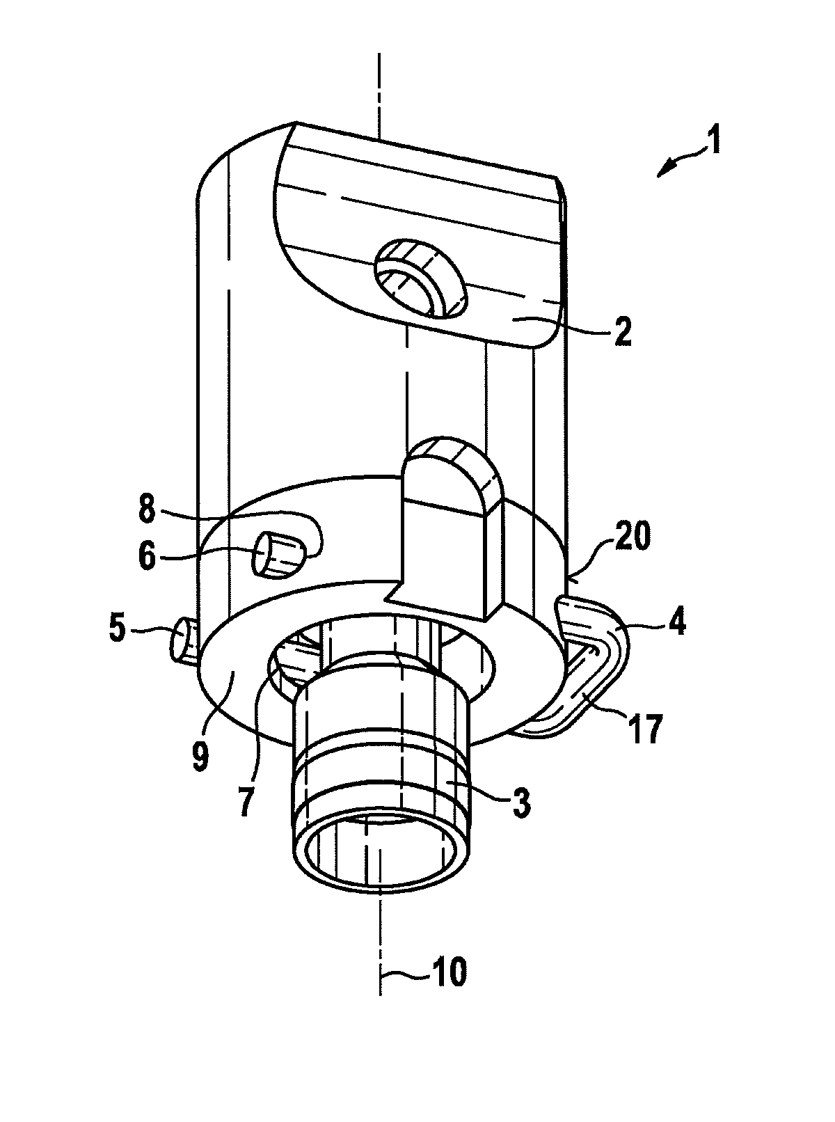
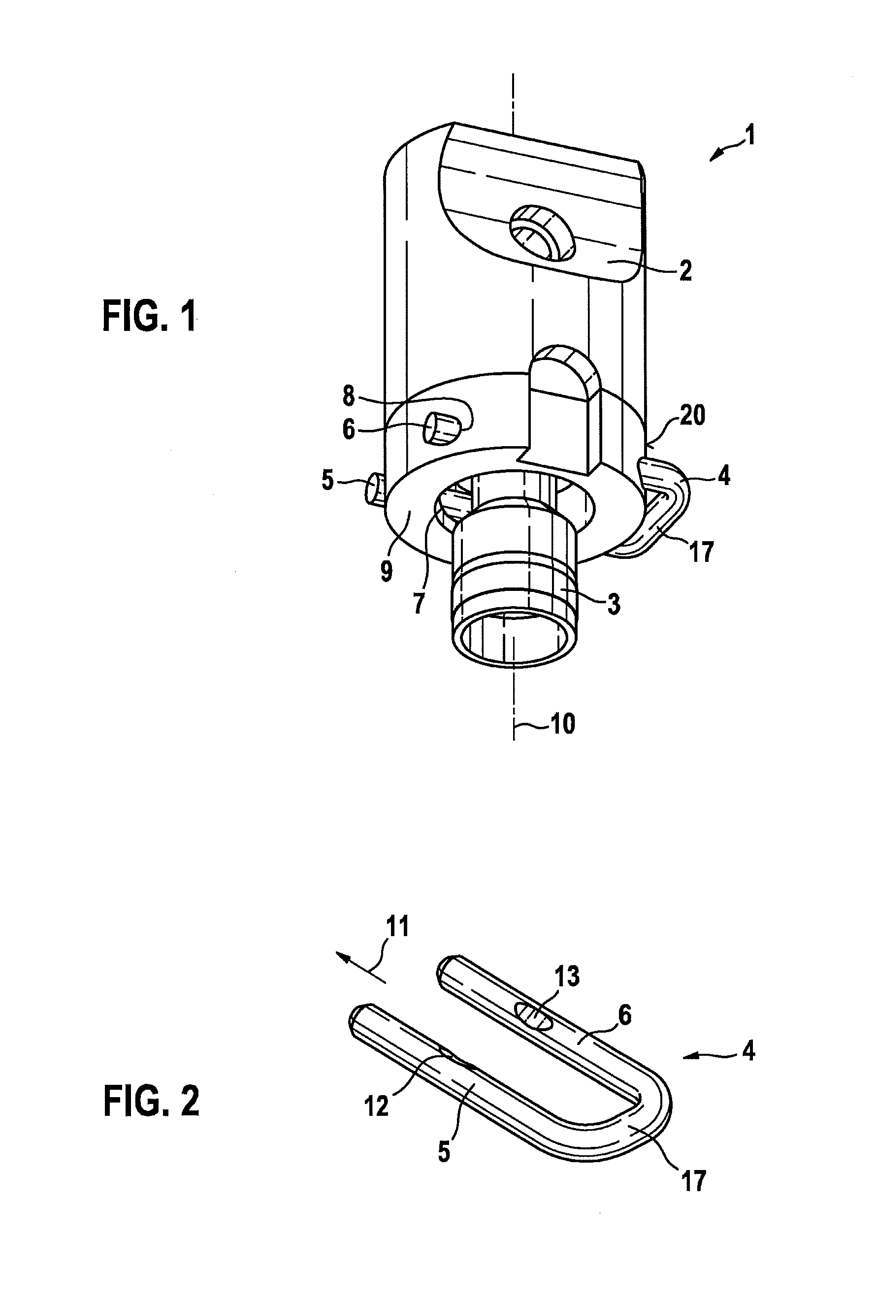
[0025]FIG. 1 shows an excerpted schematic three-dimensional view of a system 1 having a cup 2 and a connection sleeve 3 of a fuel injector, according to a first exemplary embodiment. System 1 has a plurality of such cups 2, which are interconnected via a preferably longitudinal tubular base element. This forms a fuel distributor, which may be developed as fuel distributor rail, in particular. The fuel injectors are situated on cups 2 of the fuel distributor. System 1 may therefore be developed as a fuel-injection system for the high-pressure injection in internal combustion engines, in particular. Fuel under high pressure is able to be supplied to the fuel distributor via a high-pressure pump.

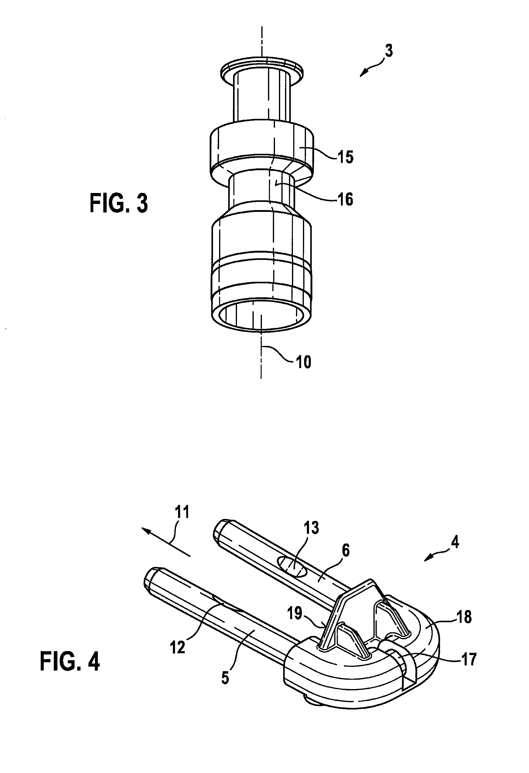
[0026]Partially illustrated connection sleeve 3 of a fuel injector is connected to cup 2 by way of a holding element 4. Holding element 4 has at least essentially straight legs 5, 6, which are guided through at least one recess 7, 8 in a wall 9 of cup 2. In this exemplary embodiment, two recess...


PUM


Abstract

A system, which is used especially as a fuel injection system for the high-pressure injection in internal combustion engines, includes a fuel distributor and a plurality of fuel injectors. Each fuel injector is situated on a cup of the fuel distributor. At least one of the fuel injectors is fastened to the associated cup by a holding element. The holding element has an at least essentially straight first leg and an at least essentially straight second leg. The cup includes at least one recess, which extends through a wall of the cup. The first leg and the second leg are guided through the at least one recess. Furthermore, the connection sleeve of the fuel injector has a collar, which is braced on the first leg of the holding element and on the second leg of the holding element in order to secure the fuel injector on the cup. This makes it possible to fasten the fuel injector on the cup in a reliable manner.

Description

FIELD OF THE INVENTION[0001]The present invention relates to a system, especially a fuel injection system, for the high-pressure injection in internal combustion engines, having a fuel distributor and multiple fuel injectors. The present invention more specifically pertains to the field of fuel-injection systems for mixture-compressing internal combustion engine featuring external ignition, in which fuel is injected directly into the combustion chambers of the internal combustion engine.BACKGROUND INFORMATION[0002]German Published Patent Application No. 10 2005 020 380 describes a fuel injection device which is characterized by a noise-decoupling design. The known fuel injection device includes at least one fuel injector, a holder for the fuel injector in a cylinder head, and a fuel distributor line provided with a pipe connection, into which the fuel injector is inserted in a partially overlapping manner. A holding-down clamp is provided between the fuel injector and pipe connectio...

Claims


Application Information

Patent Timeline
Patent Type & Authority Applications(United States)
IPC IPC(8): F02M61/14F02M41/00
CPCF02M41/00F02M61/14F02M61/168F02M2200/8023F02M2200/853F02M55/02F02M61/16Y02T10/12
Inventor POHLMANN, JENSBOLZ, THILOITTLINGER, RALPHGUENGOER, GOEKHANFROIHOFER, THOMAS
Owner ROBERT BOSCH GMBH
Why Eureka
Try Eureka