
Systems and methods for MEMS gyroscope shock robustness

a gyroscope and shock robustness technology, applied in the field of rate sensors, can solve the problems of spurious output signals that falsify the sensor's reading, negatively affecting the excitation and rate measurement of the sensor, and affecting the shock robustness of the sensor, so as to achieve the effect of increasing the shock robustness

Active Publication Date: 2015-11-19
HANKING ELECTRONICS LTD
View PDF4 Cites 68 Cited by
  • Summary
  • Abstract
  • Description
  • Claims
  • Application Information

AI Technical Summary

Benefits of technology

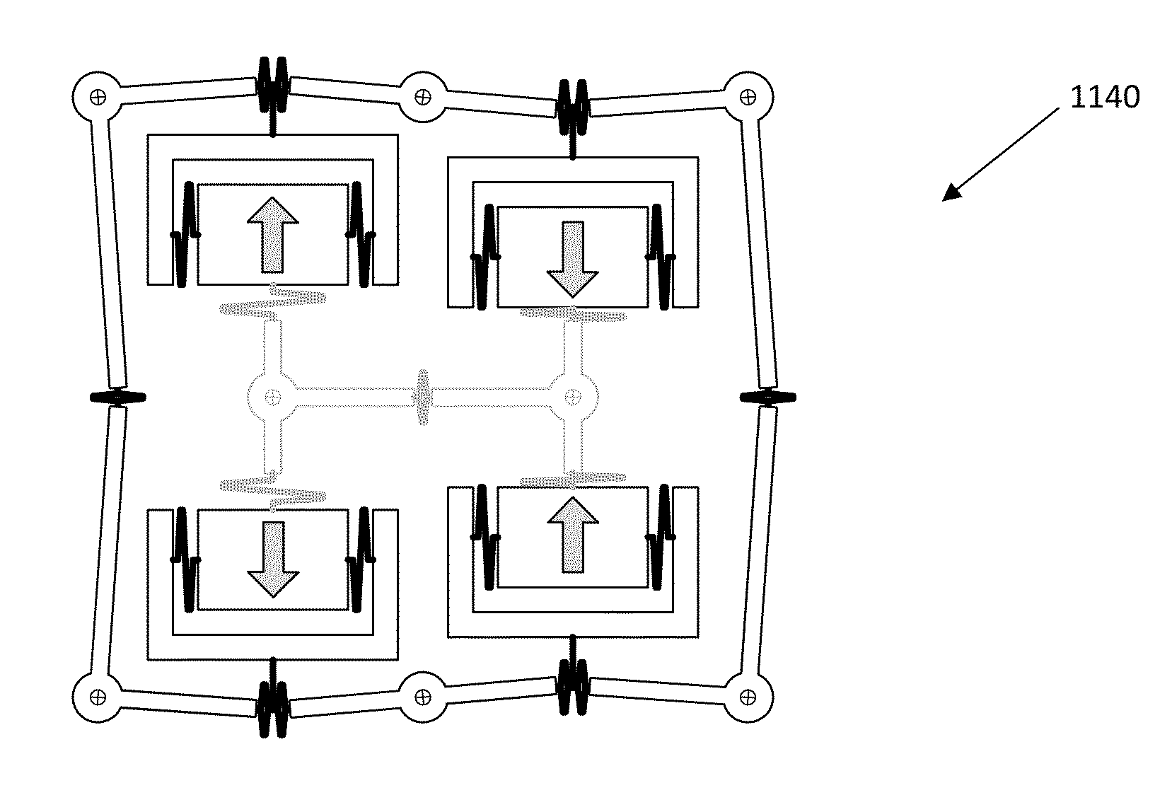
The patent text describes a system and method that improves the shock resistance of both single-axis and multi-axis rate sensors, such as gyroscopes. It does this by using a chessboard-pattern architecture of proof masses that provide a second layer of differential signals not present in existing designs. The electrodes located underneath the movable proof masses are arranged in a chessboard-pattern and connected as balanced differential pairs in order to electrically cancel the effect of mechanical disturbances such as linear and angular accelerations. The system also includes a mechanical joint system to prevent displaced movements caused by unwanted movements. Overall, this technology ensures accurate sensor readings and prevents sensor malfunctions in the face of shock and vibration.

Problems solved by technology

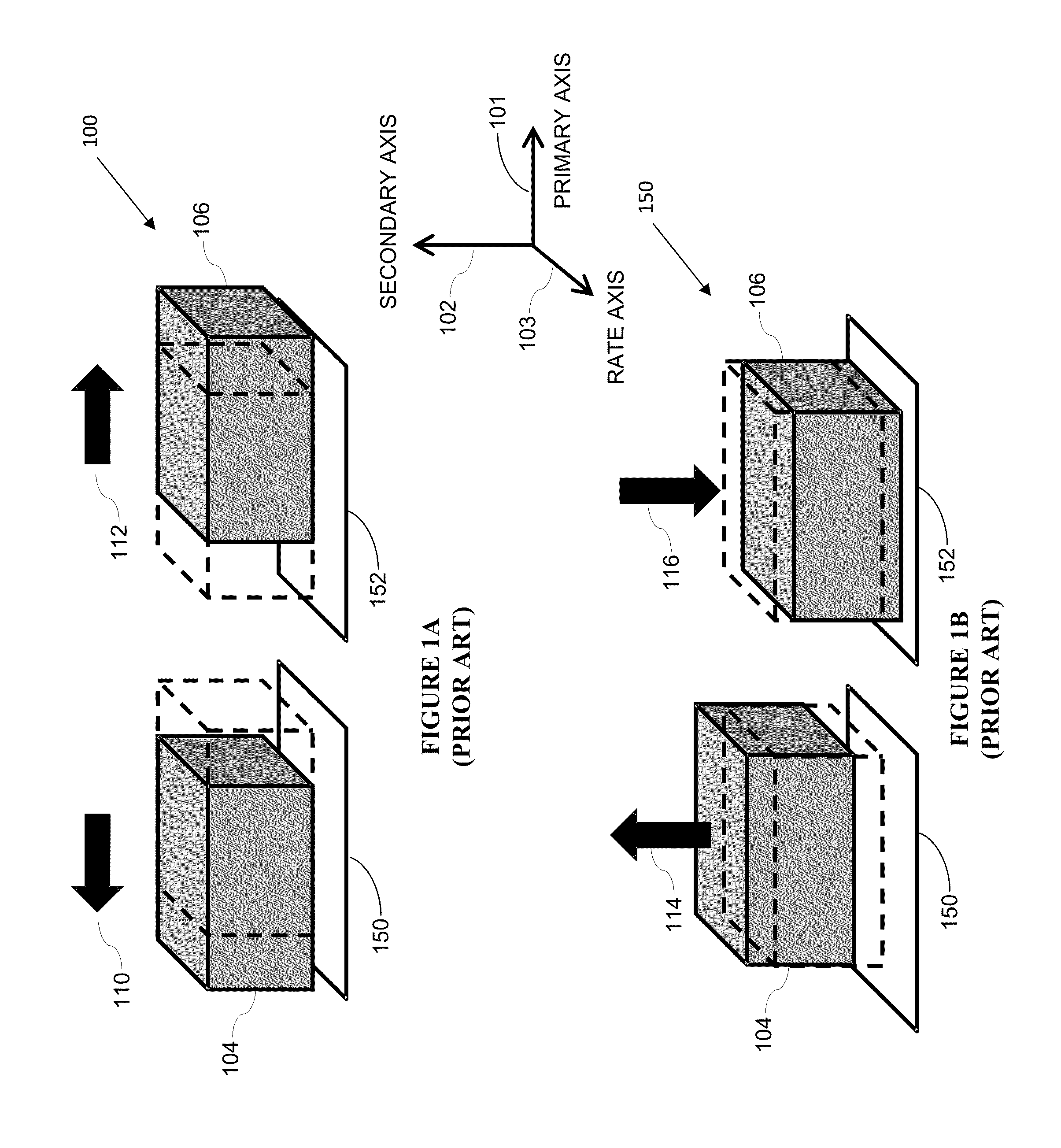
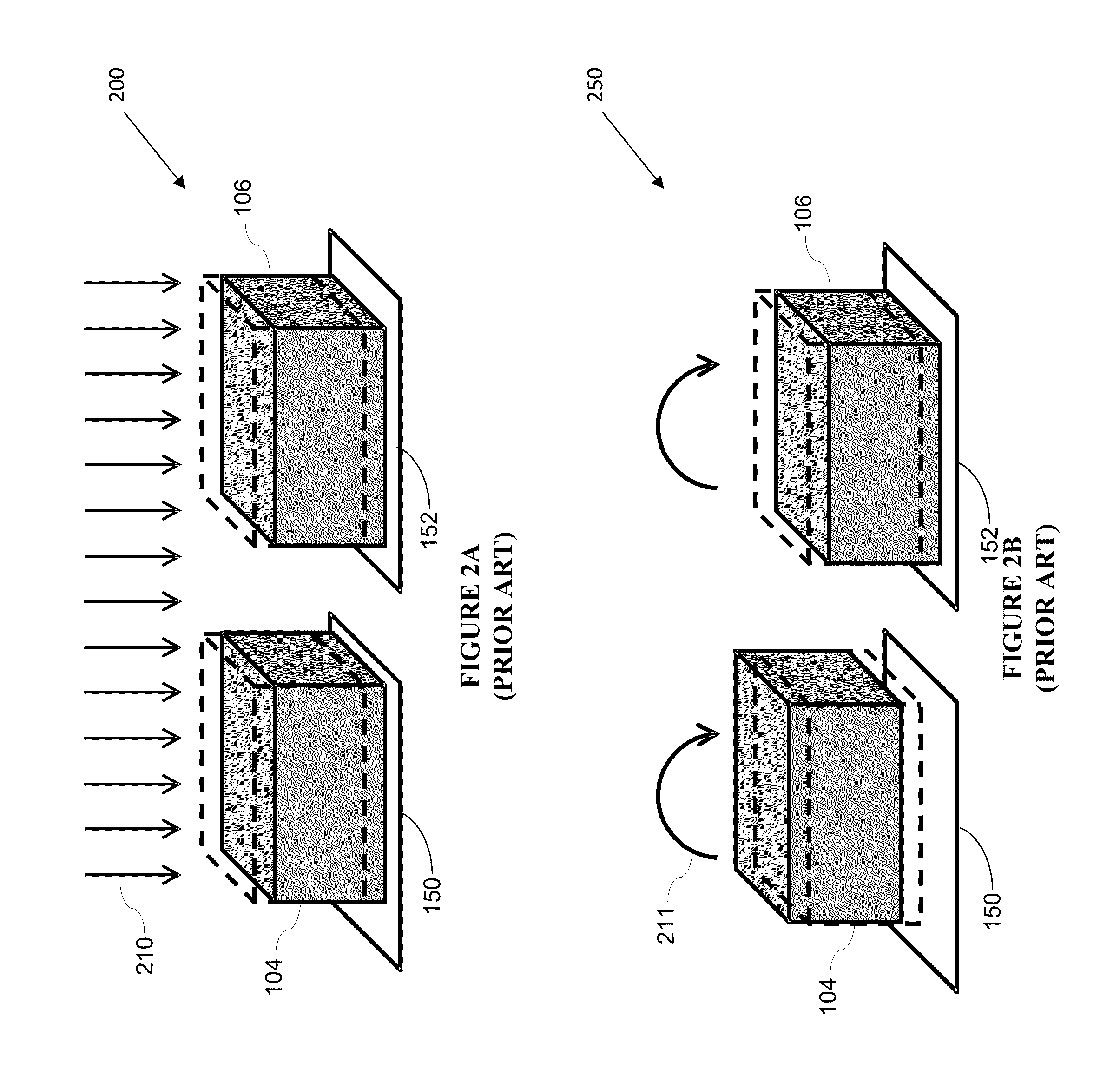
A common problem of MEMS gyroscopes is that it may be exposed to different types of external mechanical disturbances, such as shock, vibrations, and other undesirable environmental mechanical noise that can negatively impact the sensor's excitation and rate measurement.
External mechanical disturbances have numerous side effects, including the creation of spurious output signals that falsify the sensor's reading, e.g., when a shock event induces a deflection similar to a to-be-detected deflection created by a Coriolis force.
The two superimposing signals may corrupt the rate measurement.
Second, when shock events are great enough to cause the proof masses within the gyroscope to contact stopper structures that are attached to the substrate and designed to limit the displaceability of the masses, they lose some of their kinetic energy, and the sensor's primary oscillation will have to be restarted during which time the entire device remains inoperable.

Method used


Image

  • Systems and methods for MEMS gyroscope shock robustness
  • Systems and methods for MEMS gyroscope shock robustness
  • Systems and methods for MEMS gyroscope shock robustness

Examples


Embodiment Construction

[0042]In the following description, for the purpose of explanation, specific details are set forth in order to provide an understanding of the invention. It will be apparent, however, to one skilled in the art that the invention can be practiced without these details. One skilled in the art will recognize that embodiments of the present invention, described below, may be performed in a variety of ways and using a variety of means. Those skilled in the art will also recognize that additional modifications, applications, and embodiments are within the scope thereof, as are additional fields in which the invention may provide utility. Accordingly, the embodiments described below are illustrative of specific embodiments of the invention and are meant to avoid obscuring the invention.

[0043]Reference in the specification to “one embodiment” or “an embodiment” means that a particular feature, structure, characteristic, or function described in connection with the embodiment is included in ...


PUM


Abstract

Various embodiments of the invention allow for increased shock robustness in gyroscopes. In certain embodiments, immunity against undesired forces that corrupt signal output is provided by a chessboard-pattern architecture of proof masses that provides a second layer of differential signals not present in existing designs. Masses are aligned parallel to each other in a two-by-two configuration with two orthogonal symmetry axes. The masses are driven to oscillate in such a way that each mass moves anti-parallel to an adjacent proof mass. In some embodiments of the invention, a mechanical joint system interconnects proof masses to suppress displacements due to mechanical disturbances, while permitting displacements due to Coriolis forces to prevented erroneous sensor signals.

Description

CROSS REFERENCE TO RELATED PATENT APPLICATIONS[0001]The present application claims priority to U.S. Provisional Application Ser. No. 61 / 993,626 titled “Systems and Methods for MEMS Gyroscope Shock Robustness,” filed May 15, 2014. by Alessandro Rocchi, Lorenzo Bertini, and Eleonora Marchetti, which application is hereby incorporated herein by reference in its entirety and from which application priority is hereby claimed.BACKGROUND[0002]A. Technical Field[0003]The present invention relates to rate sensors. More particularly, the invention relates to systems, devices, and methods of providing shock robustness for MEMS rate of rotation sensors, such as gyroscopes.[0004]B. Background of the Invention[0005]MEMS gyroscopes are sensors that when continuously excited by driving electronics to perform a primary oscillation can sense a rotation rate about one or more axes by detecting deflections of mechanical structures that result from forces caused by the Coriolis effect.[0006]A common pro...

Claims


Application Information

Patent Timeline
Patent Type & Authority Applications(United States)
IPC IPC(8): G01C19/574G01C19/5769
CPCG01C19/5769G01C19/574G01C19/5747
Inventor ROCCHI, ALESSANDROBERTINI, LORENZOMARCHETTI, ELEANOR
Owner HANKING ELECTRONICS LTD
Learn More