
Electromechanical fuse for differential motion sensing

a technology of electrically-mechanical fuse and differential motion, which is applied in the direction of electric switches, electrical apparatus, layers, etc., can solve the problems of fuse fracturing, fuse insulation according to existing designs is prone to such fracturing, and the fuse can skew the panel

Inactive Publication Date: 2015-11-19
HAMILTON SUNDSTRAND CORP
View PDF25 Cites 2 Cited by
  • Summary
  • Abstract
  • Description
  • Claims
  • Application Information

AI Technical Summary

Benefits of technology

The patent describes a fuse that is made with a conductive metal and insulation. This fuse has a larger net section, is low-strength, has a low tensile "fracture" strength, and is designed to be sensitive to panel skew and bending strengths. The insulation is thick for durability but maintains the same low strength. The fuse can be used in any differential-motion-sensing system and can also act as a discriminator in a larger system by allowing a more sensitive load to be used, reducing the possibility of a dormant failure.

Problems solved by technology

Upon malfunction of one or more of these panels, the fuse fractures.
Due to normal handling of the sensor during manufacturing, assembly, and installation thereof onto the aircraft and / or thermal stresses of the fuse, insulation of the fuse according to existing designs is prone to such fracturing.
Also, in operation of the sensor, skew of a panel can occur such that the fuse is loaded in tension in a direction perpendicular to “height” and “width” directions of the fuse.

Method used


Image

  • Electromechanical fuse for differential motion sensing
  • Electromechanical fuse for differential motion sensing
  • Electromechanical fuse for differential motion sensing

Examples


Embodiment Construction

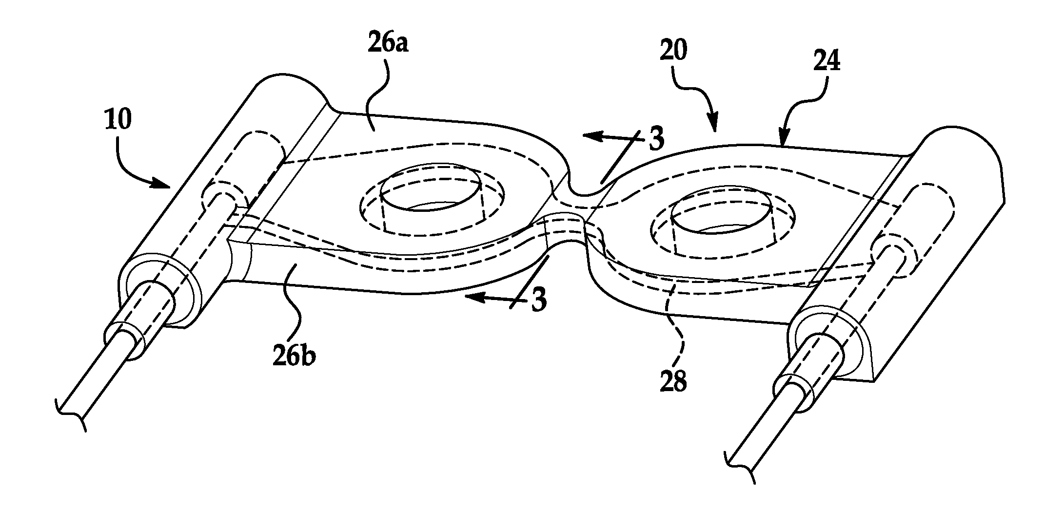
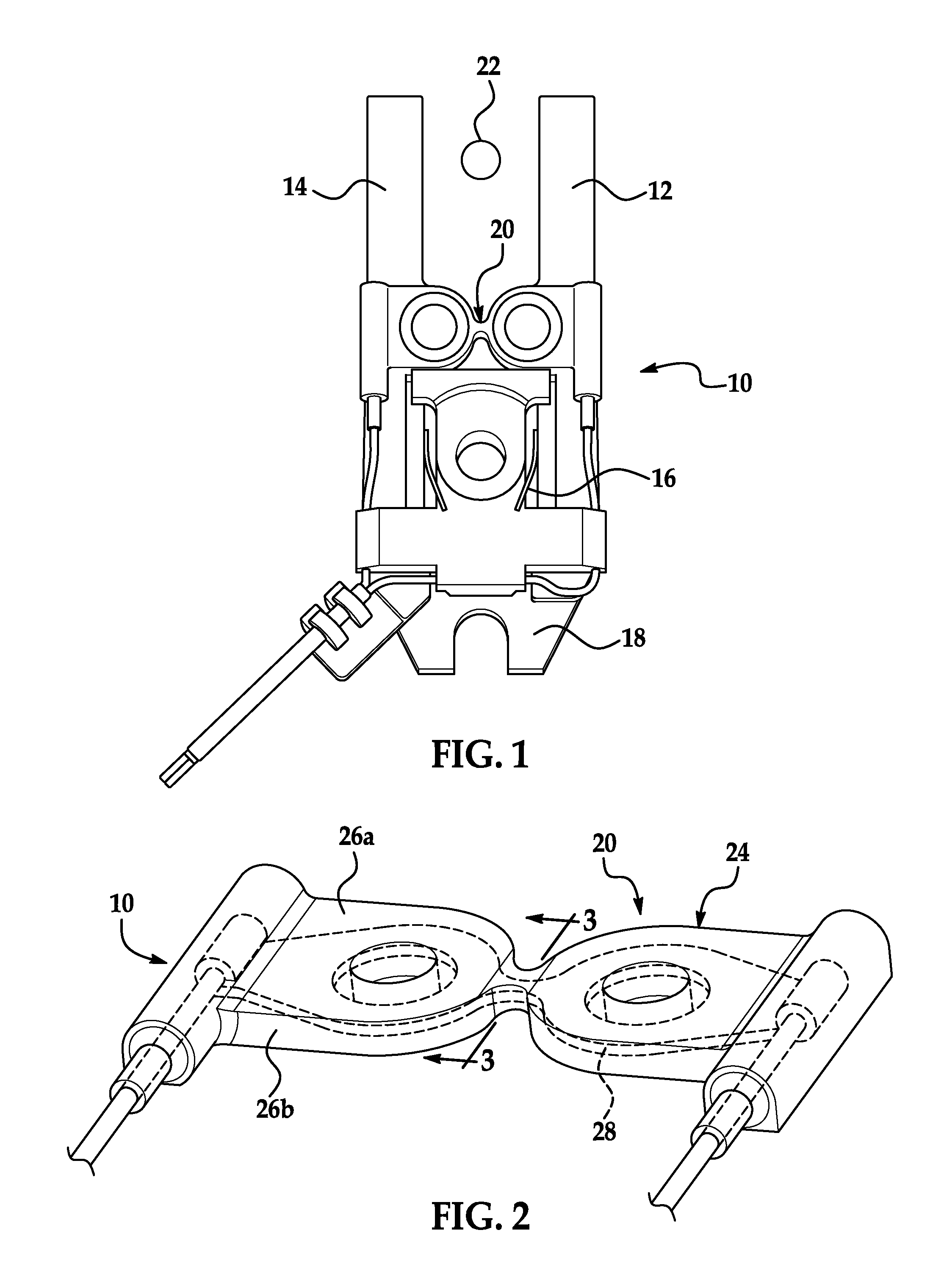
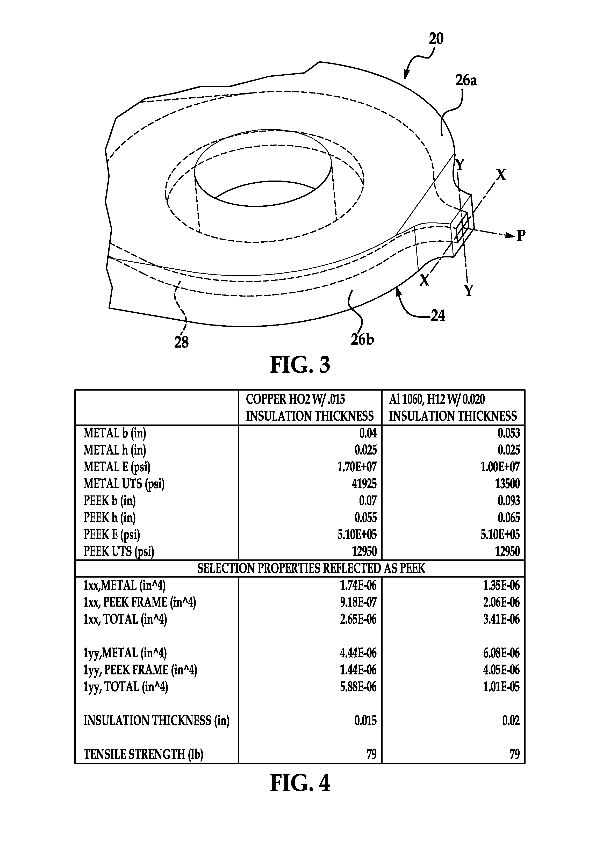
[0013]Referring now to the figures, a non-limiting embodiment of an electromechanical fuse of a differential motion sensor according to the invention is shown at 20. Although the fuse 20 is disclosed herein as electromechanical, it should be appreciated that the fuse 20 can be any suitable type of fuse. Furthermore, although the fuse 20 is so disclosed as being implemented for a differential motion sensor of an actuation system of an aircraft, it should be appreciated also that the fuse 20 can be implemented for any suitable differential-motion-sensing system or even any suitable type of sensor.

[0014]Referring now specifically to FIG. 1, a differential motion sensor with which the fuse 20 can be employed is shown at 10. The sensor 10 includes two separate arms 12, 14 biased away from one another by a separation spring 16. Each arm 12, 14 is hingedly connected to a base 18. The fuse 20 is provided between the arms 12, 14 and connects the arms 12, 14 to each other, holding the arms 12...


PUM


Abstract

An electromechanical fuse of a differential motion sensor is provided. The fuse includes at least one thick layer that acts as an insulating envelope of the fuse. A thin layer acts as a conductor of the fuse and is made of a lower-strength material.

Description

BACKGROUND OF INVENTION[0001]This invention relates, generally, to a differential motion sensor that may be employed with, for example, an actuation system of an aircraft and, more specifically, to an electromechanical fuse thereof.[0002]A differential motion sensor, such as a slat disconnect sensor, uses an electromechanical fuse. The fuse is disposed between two arms of the sensor and carries a low voltage signal that, when interrupted, annunciates a fault to a controller of, for example, an actuation system of an aircraft. The sensor may be in communication with mechanical linkages (e.g., panels of a wing of the aircraft) designed to move together. Upon malfunction of one or more of these panels, the fuse fractures. Existing designs of the fuse define a small cross-section of the fuse, use steel or copper alloys as a conductor for the fuse, and have thin insulating coatings.[0003]If tensile “fracture” load or strength of the fuse is too great, the fuse can drive an adjacent panel...

Claims


Application Information

Patent Timeline
Patent Type & Authority Applications(United States)
IPC IPC(8): H01H35/00
CPCH01H35/006H01H2209/014H01H2209/032H01H2209/002H01H2209/016H01H2209/012H01H85/10H01H2085/0034
Inventor CARBONE, MICHAELMALIK, KUNDAN LAL
Owner HAMILTON SUNDSTRAND CORP
Learn More