Pre-stressing damping system

a damping system and pre-stress technology, applied in the field of tool holders, can solve the problems of reducing speed and/or feeding speed, affecting the performance of concrete systems, and causing vibration, so as to reduce chucking forces and simplify the manipulation of tool holders.

Active Publication Date: 2015-11-26
FRANZ HAIMER MASCHINENBAU KG
View PDF14 Cites 5 Cited by
  • Summary
  • Abstract
  • Description
  • Claims
  • Application Information

AI Technical Summary

Benefits of technology

[0026]Preferably, the bush, on its face end toward the free end of the tool holder, is welded to the tool holder. This simplifies the manipulation of the tool holder, since it is ensured that the bush on being installed in and removed from the respective tool is not pulled out of the tool holder unintentionally.
[0027]It has surprisingly proved especially favorable to embody the entire bush as especially thin-walled and preferably to lend it a wall thickness <2.5 mm, and ideally <1.5 mm. This kind of thin-walled bush is overall so elastic that it brings precisely the optimal effect of the channels extending in the circumferential direction and at the same time also does not significantly reduce the chucking forces to be brought to bear relative to the tool shaft.
[0028]An especially major rationalization effect can be achieved if the invention is used not only for building individual tool holders but instead is built into a system for producing the described tool holders for chucking a tool shaft by frictional engagement, the tool shaft having different chucking characteristics. Expediently, such a system comprises a plurality of identically embodied main bodies of the tool holder and different bushes to be used with the main bodies of the tool holder. These bushes differ with regard to the structures machined into its outer circumferential surface and forming the channel and / or in the design of the clamping surface on their inner circumferential surface. In this way, one and the same main body of the tool holder can be very simply adapted to the most various requirements.

Problems solved by technology

In general in collet chucks of the described type, there is the problem that under unfavorable circumstances, because of reaction forces that originate at the cutting edges of the tool that are exposed to rapidly alternating stresses, vibration is induced, which not infrequently is in or near the resonant range.
This vibration can make itself felt so markedly in the complete system comprising the tool, collet chuck and machine tool, that the cutting speed and / or the feeding speed have to be reduced, which impairs the performance of the concrete system and is therefore unwanted.

Method used


Image

  • Pre-stressing damping system
  • Pre-stressing damping system
  • Pre-stressing damping system

Examples


Embodiment Construction

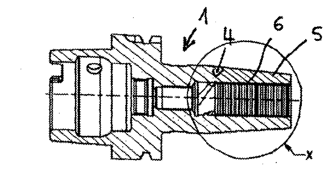
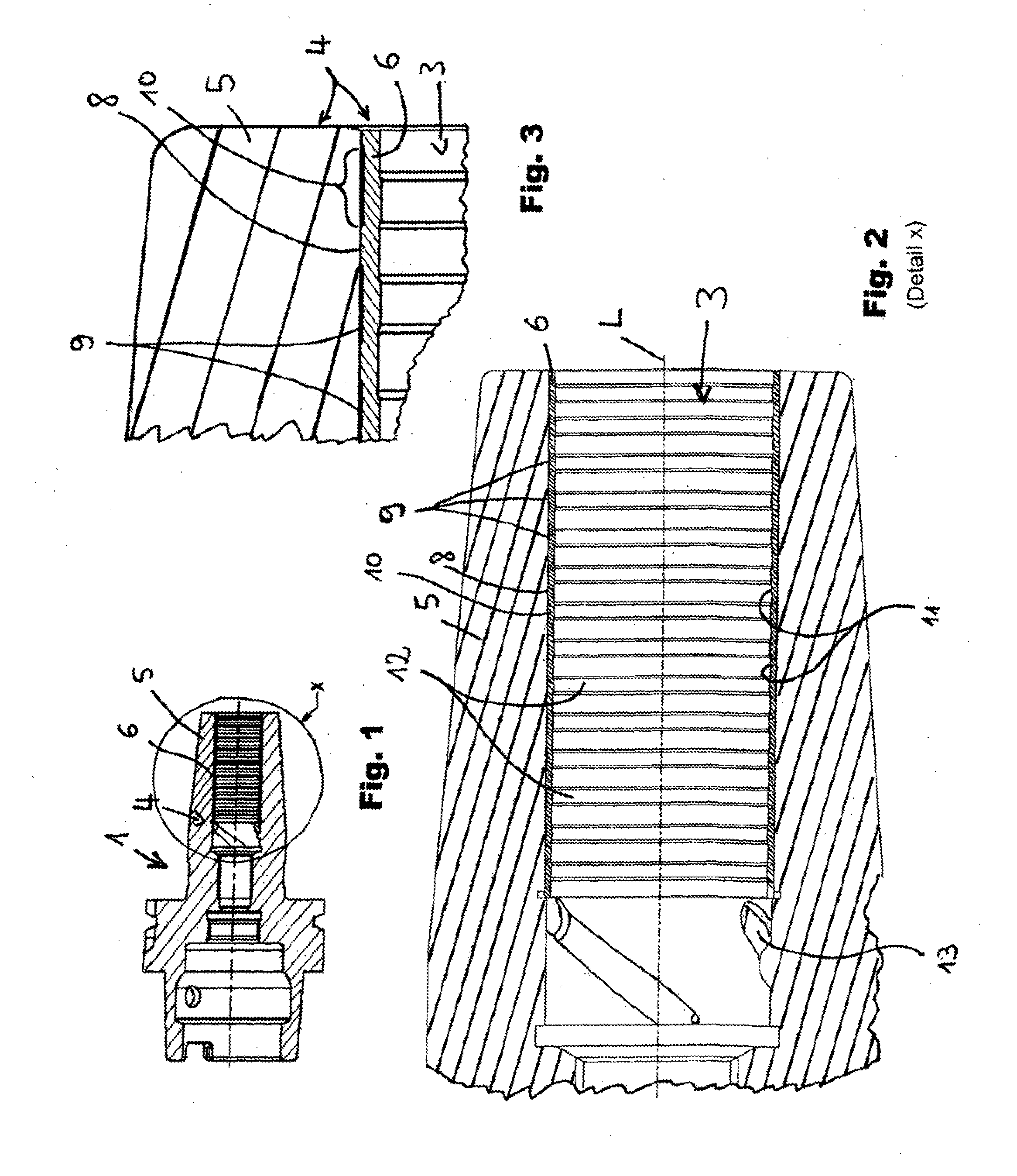
[0064]FIG. 1 shows a tool holder 1 in the form of a shrink-fit chuck. The reference symbol L designates the axis of rotation of the tool holder about which the tool holder rotates when being used as intended.

[0065]Shrink-fit chucks are capable of chucking the shafts of tools in especially hard fashion, depending on the structural type. In many cases this is advantageous, but in all those cases in which a softer chucking is opportune, the shrink-fit chucks are especially predestined for the use of the invention.

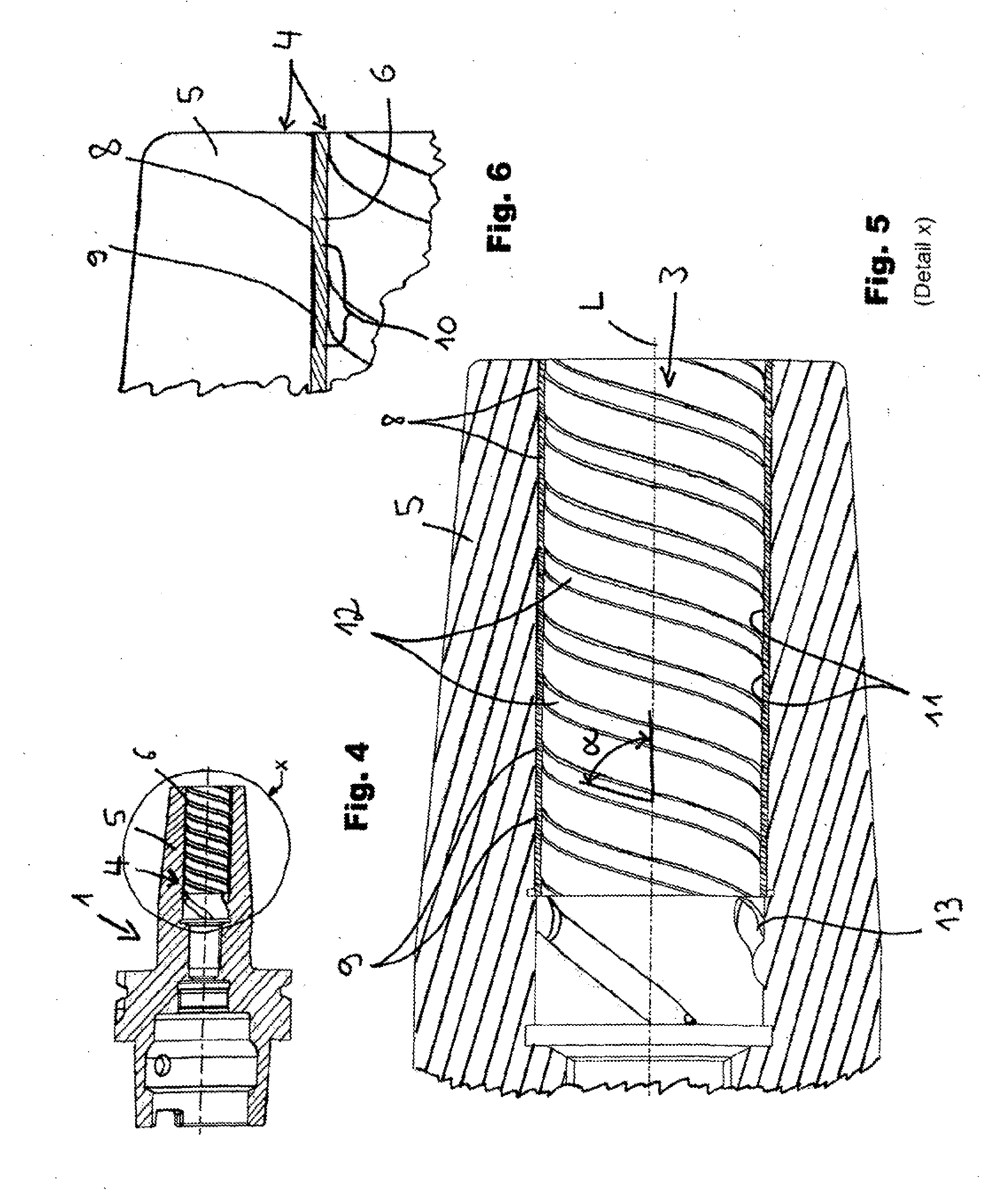
[0066]As can be seen best from FIGS. 2 and 3, this tool holder 1 has a tool receptacle 3 in the interior of its tube part 4.

[0067]The tube part 4 in this exemplary embodiment is not embodied in one piece; instead, it comprises the tubular portion 5, usually embodied as an integral component of the tool holder 1, and the bush 6 retained in this tubular portion 5.

[0068]As a rule, this bush 6 is inseparably joined to the tubular portion 5, for instance by a weld seam, not shown i...


PUM

PropertyMeasurementUnit
depthaaaaaaaaaa
thicknessaaaaaaaaaa
depthaaaaaaaaaa

Abstract

A tool holder having a tool receptacle for chucking a tool shaft by frictional engagement, in which the tool receptacle comprises a plurality of annular clamping surfaces spaced apart from one another, which are intended for retaining the tool shaft by nonpositive engagement and are embodied on the inner circumference of a tube part, and the tube part has a recess in the material for varying its clamping action; the recess in the material is embodied by a plurality of annular channels extending in the circumferential direction, which are each separated from the tool receptacle by a resilient wall portion, which on its side facing away from the channel embodies the respective clamping surface.

Description

FIELD OF THE INVENTION[0001]The invention relates to a tool holder for a tool, in particular in the form of a drill, milling cutter or reamer, that is rotatable about an axis of rotation.BACKGROUND OF THE INVENTION[0002]It is known for the shaft of such a tool to be held in a central receiving opening of an annular, self-contained part, most often embodied as a tube part, of a tool holder by means of a press fit. This tube part forms the end toward the tool of a tool holder of otherwise conventional design.[0003]This part or tube part of the tool holder can be widened by heating so far in the radial direction that the cold shaft of the tool can be thrust into the tube part or pulled out of it. As soon as the tube part has cooled down again, a pressure bond forms between it and the shaft of the tool, by means of which pressure bond the tool is reliably fixed in the tool holder (shrink-fit technology; see for example EP 1 353 768 B1).[0004]Alternatively, chucking can also be done hydr...

Claims


Application Information

Patent Timeline
Patent Type & Authority Applications(United States)
IPC IPC(8): B23B31/117B23B31/30B23C5/26B23B31/11
CPCB23B31/117B23B31/11B23B31/305B23C5/26Y10T407/1946B23B2231/026Y10T279/1216Y10T279/17931Y10T279/17957B23B2250/16B23B31/20B23B31/30B23B31/005B22F10/64B22F10/28B23B31/20125B23B31/202B23B31/02B23B31/1179B23B2250/12B23B2265/326B22F5/10B22F7/08B23B31/1177Y02P10/25B33Y80/00B23B31/1178
Inventor HAIMER, FRANZ
Owner FRANZ HAIMER MASCHINENBAU KG
Why Eureka
Try Eureka