System and method for fixtureless component location in assembling components

a fixtureless and component technology, applied in the direction of feeding apparatus, precision positioning equipment, soldering auxiliary devices, etc., can solve the problems of large floor space occupied by fixtures, long lead time and significant capital investmen

Inactive Publication Date: 2015-11-26
GM GLOBAL TECH OPERATIONS LLC
View PDF5 Cites 58 Cited by
  • Summary
  • Abstract
  • Description
  • Claims
  • Application Information

AI Technical Summary

Benefits of technology

[0065]In an embodiment, commanding the applicator system to apply the binder-coated particles to at least one of the first component at a first process joint interface and the second component at a second process joint interface further includes applying, with the applicator system, a single layer of binder-coated particles, having a defined thickness, to one of the first process joint interface and the second process joint interface, such that the single layer of binder-coated particles couples the first component and the second component and the thickness of the single layer of binder-coated particles maintains a required standoff distance for laser welding.
[0066]In an embodiment, commanding the applicator system to apply binder-coated particles to at least one of the first component at a first process joint interface and the second component at a second process joint interface further includes applying, with the applicator system, a first layer of binder-coated particles and a second layer of binder-coated particles to each of the first process joint interface and the second process joint interface, such that the binder-coated particles of the second layer are intermittently placed atop and between the binder-coated particles of the first layer so as to define a plurality of particle cavities along one of the first process joint interface and the second process joint interface and so as to define a plurality of particle posts along the other of the first process joint interface and the second process joint interface. The first component and second component are coupled to form the process joint, each of the plurality of particle cavities is configured to receive one of the plurality of particle posts forming an integration therebetween, such that the integration of the plurality of particle cavities and the plurality of particles posts couples the first component and the second component and maintains the required standoff distance for laser welding.

Problems solved by technology

These fixtures require an extended lead time and significant capital investment to design and manufacture prior to use in assembling the body components.
Additionally, the fixtures occupy a large amount of floor space.

Method used


Image

  • System and method for fixtureless component location in assembling components
  • System and method for fixtureless component location in assembling components
  • System and method for fixtureless component location in assembling components

Examples


Embodiment Construction

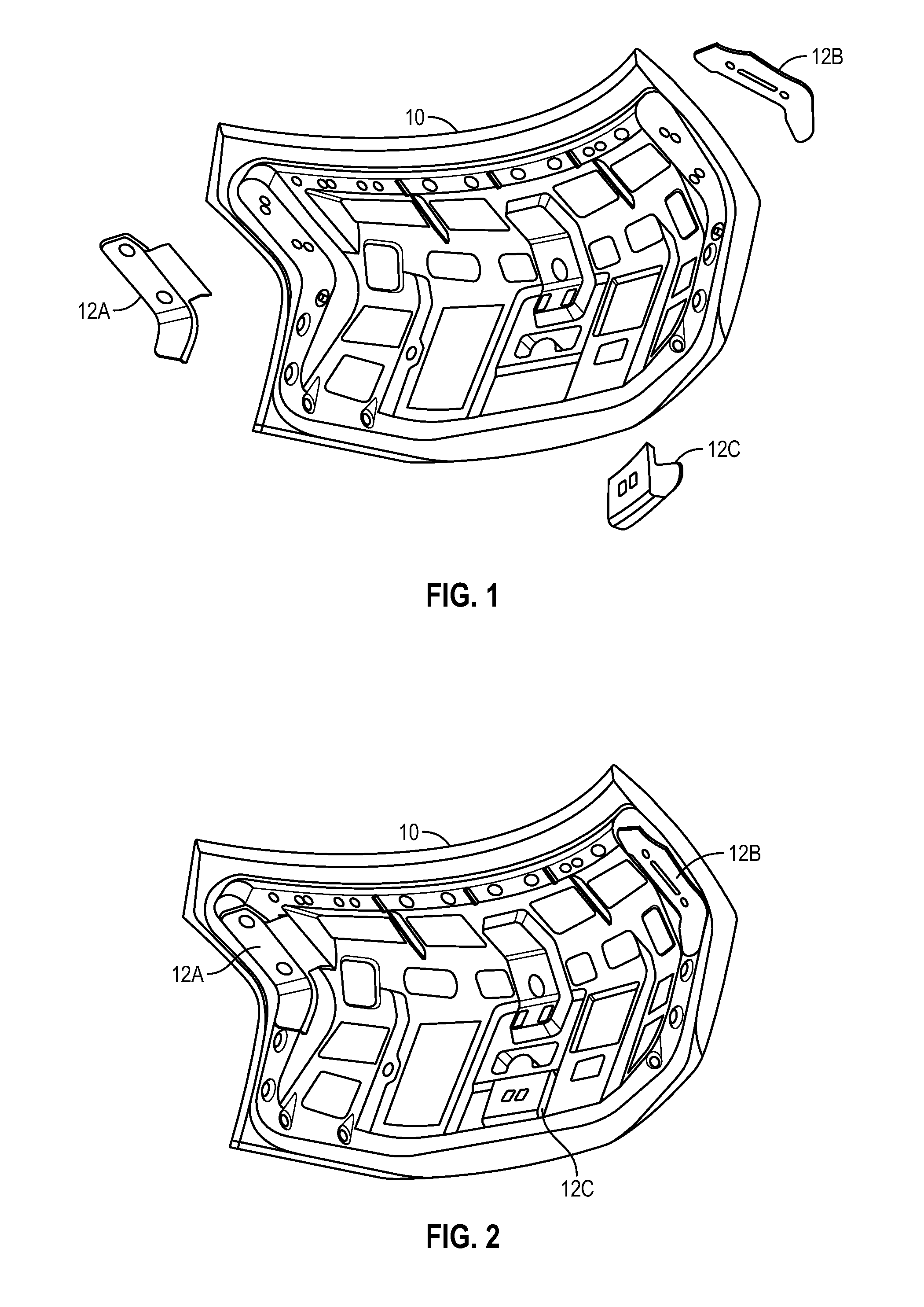
[0138]Referring to the drawings, wherein like reference numbers refer to like components throughout the views, FIG. 1 shows an exploded view of a first component 10, and multiple second components 12A, 12B, 12C. In the embodiment shown, the first component 10 is a first vehicle body component 10, and may be referred to as such. More specifically, the first vehicle body component 10 is a deck lid inner panel. The second components 12A, 12B, 12C are reinforcement components for the first vehicle body component 10, and may be referred to as second vehicle body components. The reference numeral 12 may also be used in reference to any of the second vehicle components 12A, 12B, 12C. FIG. 2 shows the first component 10 and the second components 12A, 12B, 12C after completed assembly. As discussed herein, the assembly of the first vehicle component 10 and the second vehicle components 12A, 12B, 12C is accomplished without the use of dedicated fixtures to present, position, or hold the compo...


PUM

PropertyMeasurementUnit
standoff distanceaaaaaaaaaa

Abstract

A system for assembling a first component and a second component comprises a support operatively supporting the first component without any fixtures, a vision system configured to view the supported first component and the second component and determine the locations thereof, a robotic system configured to move and position the second component relative to the first component, and a controller operatively connected to the vision system and to the robotic system and operable to control the robotic system to position the second component relative to the first component based on the locations determined by the vision system. Various methods of assembling the first component and the second component are provided to create a process joint prior to creation of a structural joint in a subsequent assembly operation.

Description

CROSS-REFERENCE TO RELATED APPLICATIONS[0001]This application claims the benefit of U.S. Provisional Application No. 62 / 000,829, filed May 20, 2014; U.S. Provisional Application No. 62 / 008,659, filed Jun. 6, 2014; U.S. Provisional Application No. 62 / 008,660, filed Jun. 6, 2014; U.S. Provisional Application No. 62 / 008,663, filed Jun. 6, 2014; U.S. Provisional Application No. 62 / 000,823, filed May 20, 2014; and U.S. Provisional Application No. 62 / 079,326, filed Nov. 13, 2014, which are hereby incorporated by reference in their entirety.TECHNICAL FIELD[0002]The present teachings generally include a system and a method for component locating during assembly of assembling multiple component items, such as but not limited to vehicle body components, boats, construction equipment, lawn equipment, or robots.BACKGROUND[0003]Vehicle bodies are comprised of a multitude of structural components that must be assembled to one another with sufficient precision for proper function and aesthetics. T...

Claims


Application Information

Patent Timeline
Patent Type & Authority Applications(United States)
IPC IPC(8): B25J9/16B23P19/04B32B7/14B25J19/02B32B37/26B32B41/00B23K31/12B23K37/04B23P15/00B32B7/06
CPCB25J9/1687Y10T29/53061B23P19/04B32B7/14B32B7/06B32B37/26B32B41/00B23K31/12B23K37/04B25J9/1697B25J19/02B25J9/1682B23P2700/50B32B2037/268Y10S901/09Y10T428/24802Y10T29/49771B23P15/00B23K26/032B23K26/21B23K31/125B23K37/0426B23K37/0443B23K37/047B23K2101/006B23K2101/34B23K2103/08C09J5/00
Inventor SPICER, JOHN PATRICKLIN, YHU-TINSEKOL, RYAN C.MCKAY, NEIL DAVIDSHI, JIANYINGSMITH, MARK A.TILOVE, ROBERT BRUCEABDALLAH, MUHAMMAD E.OH, SEOG-CHANGUO, RAYMONDRANSOM, LANCE T.
Owner GM GLOBAL TECH OPERATIONS LLC
Why Eureka
Try Eureka